son
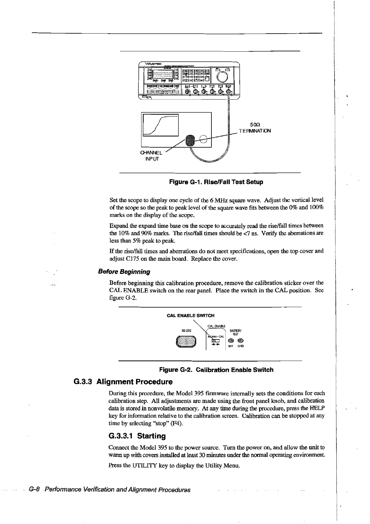
TE
RIII1lNAT
ION
a-lANNEL
INPUT
Figure G-1. Rise/Fall Test Setup
Setthe scope to display one cycle
of
the 6
MHz
square wave. Adjust the verticaIlevel
of
the scope so the
peak:
to peak level
of
the square wave fits between the
0%
and 100%
marks on the display
of
the scope.
Expand the expand time base on the scope to accurately read the rise/fall times between
the 10% and 90% marks. The rise/faIl times should
be
<7 ns.
Veri.fY
the aberrations are
less than 5% peak to peak.
If
the rise/faU times and aberrations
do
not meet specifications, open the top cover and
adjust C175 on the main board. Replace
the
coyer.
Before Beginning
Before beginning fuis calibration procedure, remove the calibration sticker
over
the
CAL
ENABLE switch on the
rear
panel. Place the switch in the
CAL
position. See
figure G-2.
Figure G-2. Calibration Enable Switch
G.3.3 Alignment Procedure
During this procedure, the Model 395 frrmware internally sets the conditions for each
calibration step. AlI adjustments are made using the front panel knob,
and
calibration
datais stored
in nonvolatile memory.
At
any time during the procedure, press the HELP
key for information relative to the calibration screen. Calibration can
be
stopped
at
any
time by selecting "stop" (F4).
G.3.3.1 Starting
Connect the Model 395
ta
the power source. Torn the
power
on,
and
allow
the
unit
to
warm up withcovers installedat least 30minutes underthe normal opemting environment.
Press the
UTILI1Y
key to display the Utility Menu.
G-8 Performance Verification andAlignment Procedures
Artisan Technology Group - Quality Instrumentation ... Guaranteed | (888) 88-SOURCE | www.artisantg.com