MB95630H Series
270 FUJITSU SEMICONDUCTOR LIMITED MN702-00009-2v0-E
CHAPTER 15 8/10-BIT A/D CONVERTER
15.5 Operations and Setting Procedure
Example
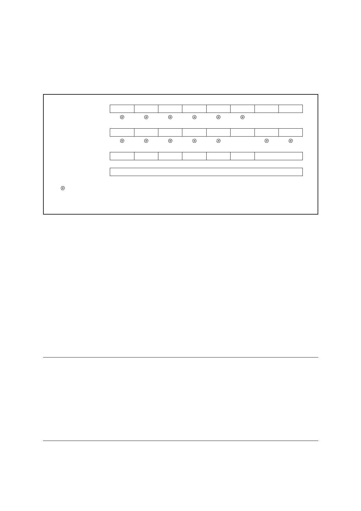
● Continuous activation
To execute continuous activation of the A/D conversion function, do the settings shown in
Figure 15.5-2.
Figure 15.5-2 Settings for A/D Conversion Function (Continuous Activation)
When continuous activation is enabled, the A/D conversion function is activated at the rising
edge of the input clock selected to start A/D conversion. Continuous activation is stopped when
disabled (ADC2:EXT = 0).
■ Operations of A/D Conversion Function
This section explains the operations of 8/10-bit A/D converter.
1. When A/D conversion is started, the conversion flag bit is set (ADC1:ADMV = 1) and the
selected analog input pin is connected to the sample-and-hold circuit.
2. The voltage in the analog input pin is loaded into a sample-and-hold capacitor in the
sample-and-hold circuit during the sampling cycle. This voltage is held until A/D
conversion is completed.
3. The comparator in the control circuit compares the voltage loaded into sample-and-hold
capacitor with the A/D conversion reference voltage, from the most significant bit (MSB)
to the least significant bit (LSB), and then transfers the results to the ADDH and ADDL
registers.
After the results have been transferred to the two registers, the conversion flag bit is cleared
(ADC1:ADMV = 0) and the interrupt request flag bit is set to "1" (ADC1:ADI = 1).
Notes:
• The contents of the ADDH and ADDL registers are saved at the end of A/D
conversion. Therefore, during A/D conversion, the values resulting from last
conversion will be returned if the two registers are read.
• Do not change the analog input pin select bits (ADC1:ANS[3:0]) while AD conversion
function is being used. During continuous activation in particular, disable continuous
activation (ADC2:EXT = 0) before changing the analog input pin.
• A reset, or the start of the stop mode or watch mode causes the A/D converter to stop
and the ADMV bit to be cleared to "0".
bit7 bit6 bit5 bit4 bit3 bit2 bit1 bit0
ADC1 ANS3 ANS2 ANS1 ANS0 ADI ADMV Reserved AD
0×
ADC2 AD8 TIM1 TIM0 ADCK ADIE EXT CKDIV1 CKDIV0
1
ADDH ------
A/D converted value retained
ADDL A/D converted value retained
: Bit to be used
× : Unused bit
0 : Set to "0"
1 : Set to "1"