MB95630H Series
296 FUJITSU SEMICONDUCTOR LIMITED MN702-00009-2v0-E
CHAPTER 17 CLOCK SUPERVISOR COUNTER
17.3 Operations
Table 17.3-1 is calculated by the following equation:
If the time-base timer interrupt is used to make the clock supervisor counter wait for the
oscillation stabilization time, please satisfy the following condition:
Time-base Timer Interval > Main Oscillation / Suboscillation Stabilization Time
× 1.05
e.g. F
CH
= 4 MHz, F
CRH
= 1 MHz, MWT[3:0] = 0b1111 (in WATR register)
Time-base Timer Interval >
TBC[3:0] = 0b0110 (2
13
× 1/F
CRH
)
Notes:
• See "7.1 Overview" for time-base timer interval settings.
• See "3.3.3 Oscillation Stabilization Wait Time Setting Register (WATR)" for main/
sub-oscillation stabilization time settings.
Counter value =
2
3
× 1/F
CRH
(TBTSEL=000)
2
5
× 1/F
CRH
(TBTSEL=001)
2
7
× 1/F
CRH
(TBTSEL=010)
2
9
× 1/F
CRH
(TBTSEL=011)
2
11
× 1/F
CRH
(TBTSEL=100)
2
13
× 1/F
CRH
(TBTSEL=101)
2
15
× 1/F
CRH
(TBTSEL=110)
2
17
× 1/F
CRH
(TBTSEL=111)
× Main/Sub-Oscillation Clock Frequency
2
± 1 (Measurement error)
*Omit the decimal places of “Counter value”.
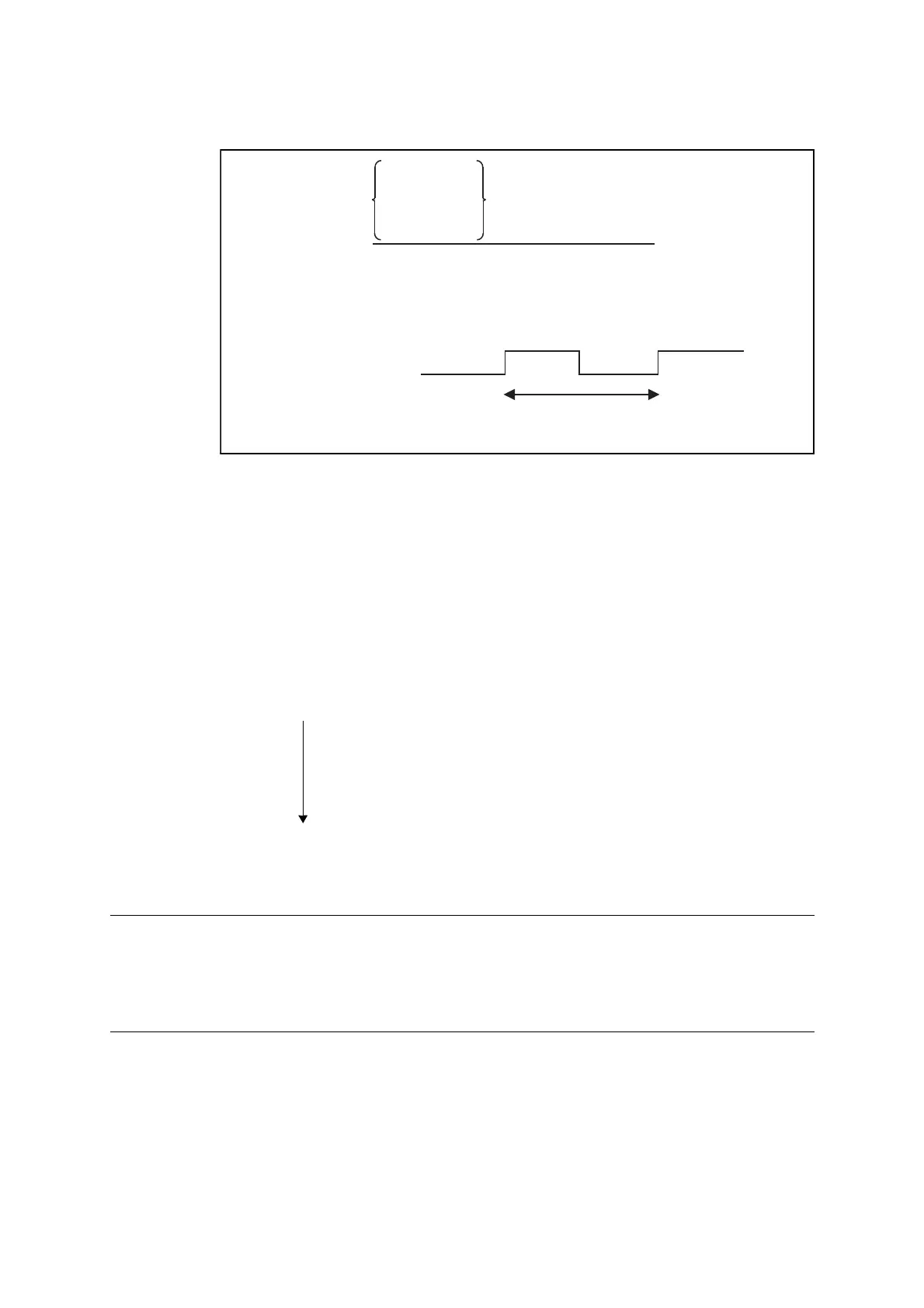
Selected time-base
timer interval
Within this period, the “Counter value” in the above equation is
counted by the main/sub oscillation clock.
2
14
2)–(
410
6
×
-----------------------
1.05 4.3 ms≈×