MB95630H Series
316 FUJITSU SEMICONDUCTOR LIMITED MN702-00009-2v0-E
CHAPTER 18 8/16-BIT PPG
18.6 Operations and Setting Procedure Example
reversed and the signal is output to the PPGn1 pin.
• When the PPG timer n0 (ch. n) downcounter operation enable bit (PEN00) is set to "1", the
8-bit PPG (PPG timer n0) loads the value in the 8/16-bit PPG timer n0 cycle setup buffer
register (PPSn0) and starts down-count operation (count clock = rising and falling edge
detection pulses of PPGn1 output after PPG timer n1 operation is enabled). When the count
value reaches "1", the value in the PPSn0 register is reloaded to repeat the counting. When
the value of the downcounter matches the value in the 8/16-bit PPG timer n0 duty setup
buffer register (PDSn0), the PPGn0 output is set to "H" synchronizing with the count clock.
After "H" which is the value of duty setting is output, the PPGn0 output is reset to "L". If
the output level reverse bit (REV00) is "0", the polarity remains the same. If it is "1", the
polarity is reversed and the signal is output to the PPGn0 pin.
• Set that the duty of the 8-bit prescaler (PPG timer n1) output to 50%.
• When PPG timer n0 is started with the 8-bit prescaler (PPG timer n1) being stopped, PPG
timer n0 does not count.
• When the duty of the 8-bit prescaler (PPG timer n1) is set to 0% or 100%, PPG timer n0
does not perform counting as the 8-bit prescaler (PPG timer n1) output does not toggle.
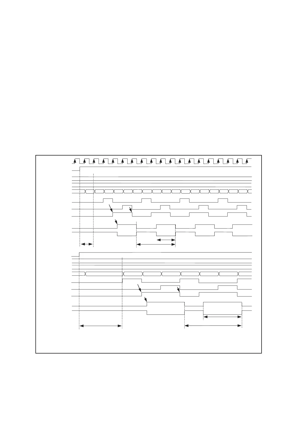
Figure 18.6-4 shows the operation of 8-bit prescaler + 8-bit PPG mode.
Figure 18.6-4 Operation of 8-bit Prescaler + 8-bit PPG Mode
m1=4
n1=2
4 3 2143 2143 2143 2
(1) = n1
×
T
(2) = m1
×
T
Synchronizing with machine clock
Synchronizing with machine clock
(1)
(2)
α
Count clock
(Cycle T)
PEN01
PPG timer n1
counter value
Downcounter value
matches matches duty
setting value
Duty setting
(PDSn1)
Cycle setting
(PPSn1)
(Normal polarity)
PPGn1
PEN00
3
PPG timer n0
counter value
m0=3
n0=2
Duty setting
(PDSn0)
Cycle setting
(PPSn0)
213 21
(Normal polarity)
PPGn0
(Inversion polarity)
(Reverse polarity)
3
14
2
(3)
β
(4)
(3) = (1)
×
n0
(4) = (1)
×
m0
Downcounter value
matches matches duty
setting value
Counter borrow
PPG output source
Counter borrow
PPG output source
T: Count clock cycle
m0: PPSn0 register value
n0: PDSn0 register value
m1: PPSn1 register value
n1: PDSn1 register value
α: The value changes depending on the count
clock selected and the PEN01 start timing.
β: The value changes depending on the
PPGn1 output (ch. n) waveform and the
PEN00 start timing.