MB95630H Series
MN702-00009-2v0-E FUJITSU SEMICONDUCTOR LIMITED 379
CHAPTER 21 MULTI-PULSE GENERATOR
21.1 Overview
• In the waveform sequencer, there is a 16-bit timer that can be used to measure the speed of
the motor and disable the OPT output in case of position detect missing.
• Forced stop control using DTTI pin input
External pin control can be performed through DTTI pin input. (The pin level can be set by
each pin or software.) There is selectable noise filter for DTTI input. Table 21.1-2 shows
the noise width for noise filter of DTTI pin.
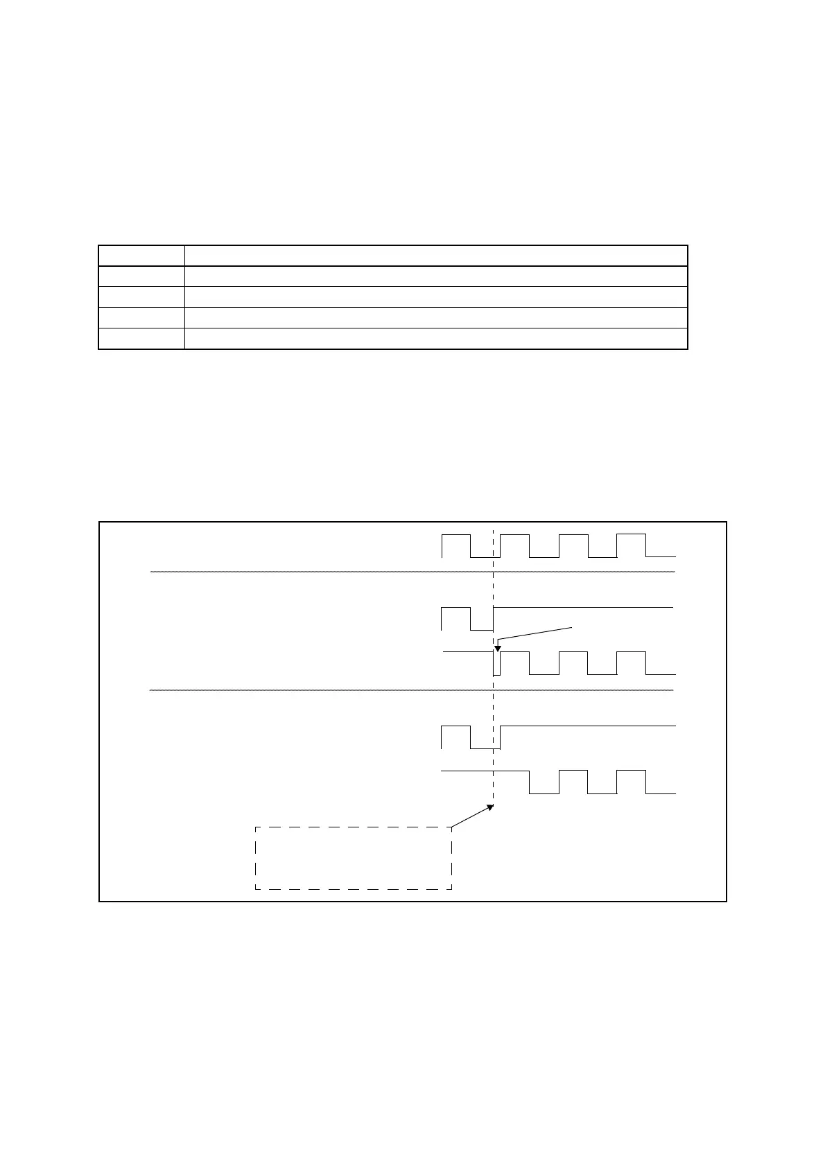
● PPG synchronization for output signal
In order to avoid short pulse (or glitch) during sequencer state changes, delay the write timing
(WTO) and synchronize it with the next coming edge of PPG output waveform. See Figure
21.1-1 and Figure 21.1-2 for details. This function can be enabled or disabled by software. The
WTS[1:0] bits in the 16-bit MPG input control register (upper) (IPCUR) are used to disable
this function and to select the polarity of the PPG edge to synchronize with.
Figure 21.1-1 PPG Rising Edge Synchronization
Table 21.1-2 Noise Width for Noise Filter
Selection Noise width for DTTI and SNI2 to SNI0 pins
1 Cancels 4-cycle noise.
2 Cancels 8-cycle noise.
3 Cancels 16-cycle noise.
4 Cancels 32-cycle noise.
OP4’
OP5’
OP4
OP5
PPG
Asynchronous State Change
Synchronous State Change
Glitch
WTS[1:0] = 0b00
WTS[1:0] = 0b01
The sequencer changes its
state (e.g. due to a reload
timer underflow).