MB95630H Series
MN702-00009-2v0-E FUJITSU SEMICONDUCTOR LIMITED 399
CHAPTER 21 MULTI-PULSE GENERATOR
21.5 Operations
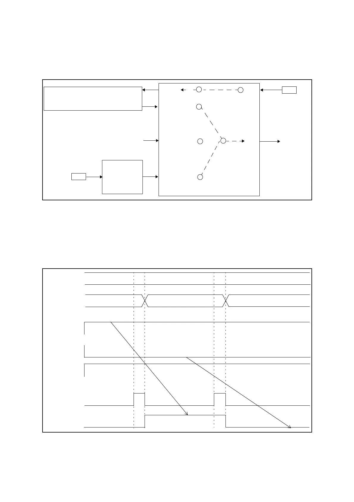
■ Signal Flow Diagram for Reload Timer or Position Detection by Setting
OPS[2:0] = 0b100 or 0b101
Figure 21.5-10 Signal Flow Diagram for Reload Timer or Position Detect (OPS[2:0] = 0b100 or
0b101)
At this setting the write signal is generated by the compare match or effective edge input of the
position detection or after an underflow occurs in the 16-bit reload timer. The compare match
is triggered by any effective edge change in SNI2 to SNI0 pins.
■ OPDUR and OPDLR Write Timing Diagram
(OPS[2:0] = 0b001, 0b010, 0b011, 0b100, 0b101, 0b110, or 0b111)
Figure 21.5-11 OPDUR and OPDLR Write Timing Diagram
(OPS[2:0] = 0b001, 0b010, 0b011, 0b100, 0b101, 0b110, or 0b111)
POSITION
16-BIT RELOAD TIMER
TIN
TOUT
DETECTION
TIN0O
WTIN0
WTIN1
WTO
TIN0
SNI2 to
TI1
WRITE
TIMING
DATA WRITE CONTROL UNIT
ODBR0W
OUTPUT
Pin
Pin
SNI0
OPDBRH0/OPDBRL0
WRITE SIGNAL
OPS[2:0]
WTO
0b001, 0b010, 0b011, 0b100, 0b101, 0b110, or 0b111
OPDBRL4[0]
BNKF,
RDA[2:0]
OPDBRL1[0]
OPDBRL7[0]
0b0100
0b0001 0b0111
OP00
(OPDUR)