MB95630H Series
22 FUJITSU SEMICONDUCTOR LIMITED MN702-00009-2v0-E
CHAPTER 3 CLOCK CONTROLLER
3.1 Overview
■ Combinations of Clock Mode and Standby Mode
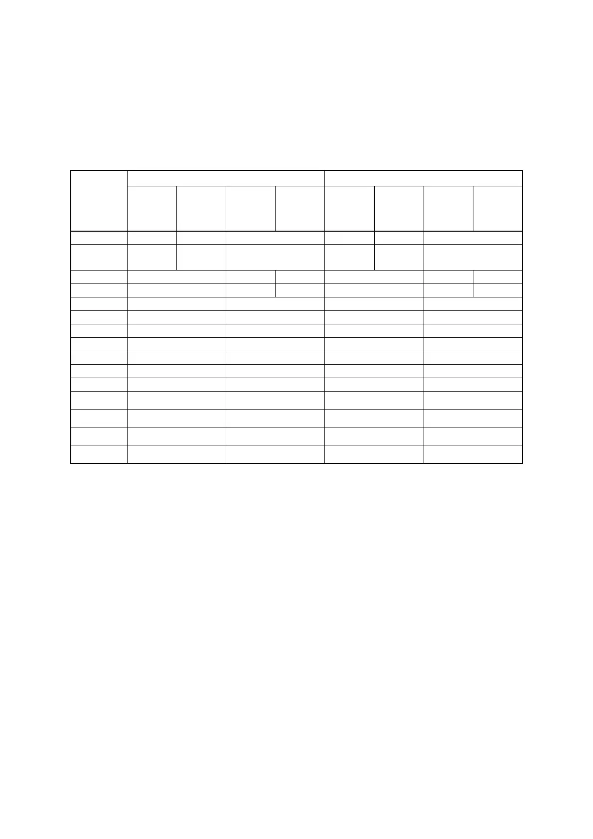
Table 3.1-3 and Table 3.1-4 list the combinations of clock mode and standby mode, and the
respective operating states of different internal circuits with different combinations of clock
mode and standby mode.
*1: The main clock runs when the main clock oscillation enable bit in the system clock control register 2
(SYCC2:MOSCE) is set to "1".
*2: The main CR clock or the main CR PLL clock runs when main CR clock oscillation enable bit in the system
clock control register 2 (SYCC2:MCRE) is set to "1".
*3: The module runs when the subclock oscillation enable bit in the system clock control register 2
(SYCC2:SOSCE) is set to "1".
*4: The module runs when the sub-CR clock oscillation enable bit in the system clock control register 2
(SYCC2:SCRE) is set to "1".
*5: The hardware watchdog timer stops when the hardware watchdog timer is disabled by the non-volatile
register (NVR) interface.
*6: The state of the Flash memory in a standby mode can be selected from two options, normal state and low-
power state, by the deep standby mode control bit in the standby control register 2 (STBC2:DSTBYX).
Table 3.1-3 Combinations of Standby Mode and Clock Mode, and Internal Operating States (1)
Function
RUN Sleep
Main clock
mode
Main CR
clock mode/
Main CR PLL
clock mode
Subclock
mode
Sub-CR
clock mode
Main clock
mode
Main CR
clock mode/
Main CR PLL
clock mode
Subclock
mode
Sub-CR
clock mode
Main clock Operating
Stopped
*1
Stopped Operating
Stopped
*1
Stopped
Main CR clock/
Main CR PLL
clock
Stopped
*2
Operating Stopped
Stopped
*2
Operating Stopped
Subclock
Operating
*3
Operating
Operating
*3
Operating
*3
Operating
Operating
*3
Sub-CR clock
Operating
*4
Operating
*4
Operating
Operating
*4
Operating
*4
Operating
CPU Operating Operating Stopped Stopped
Flash memory Operating Operating
Value held
*6
Value held
*6
RAM Operating Operating Value held Value held
I/O ports Operating Operating Output held Output held
Time-base timer Operating Stopped Operating Stopped
Watch prescaler
Operating
*3, *4
Operating
Operating
*3, *4
Operating
External interrupt Operating Operating Operating Operating
Hardware
watchdog timer
Operating Operating
Operating
*5
Operating
*5
Software watchdog
timer
Operating Operating Stopped Stopped
Low-voltage
detection reset
Operating Operating Operating Operating
Other peripheral
functions
Operating Operating Operating Operating