MB95630H Series
MN702-00009-2v0-E FUJITSU SEMICONDUCTOR LIMITED 473
CHAPTER 22 UART/SIO
22.6 Operations and Setting Procedure Example
When 5-bit to 8-bit serial data is received by the reception shift register, the received data is
transferred to the UART/SIO serial input data register ch. n (RDRn) and the next piece of serial
data can be received.
When the RDRn register stores data, the receive data register full flag bit (RDRF) is set to "1".
A receive interrupt occurs the moment the RDRF bit is set to "1" when the receive interrupt
enable bit (RIE) contains "1".
To read received data, read it from the RDRn register after checking the overrun error flag bit
(OVE) in the UART/SIO serial status and data register ch. n (SSRn).
When received data is read from the RDRn register, the RDRF bit is cleared to "0".
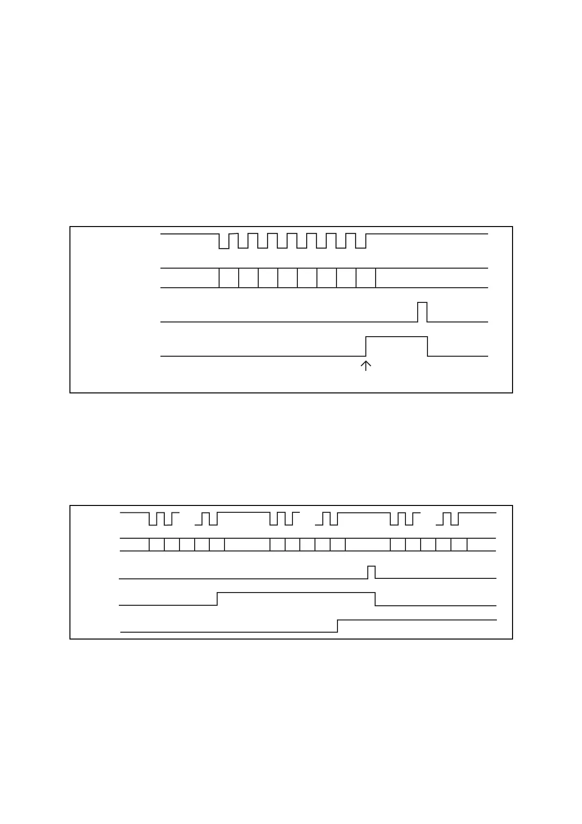
Figure 22.6-12 8-bit Reception of Synchronous Clock Mode
Operation when receive error occurs
When an overrun error (OVE = 1) occurs, received data is not transferred to the RDRn
register.
Overrun error (OVE = 1)
Upon completion of reception for serial data, the OVE bit is set to "1" if the RDRF bit has
been set to "1" by the reception for the preceding piece of data.
Figure 22.6-13 Overrun Error
UIn D0 D1 D2 D3 D4 D5 D6 D7
UCKn
Read to RDRn
RDRF
Interrupt to interrupt controller
UCKn
UIn
D0 D1 ... D6 D7 D0 D1 ... D6 D7 D0 D1
...
... ... ...
D6 D7
Read to
RDRn
RDRF
OVE