Cockpit Reference Guide for the Cirrus SR2x with Perspective Touch+ by Garmin
190-02954-01 Rev. A
190
Flight
InstrumentsEAS
Audio and
CNS
Flight
Management
Hazard
AvoidanceAFCS
Additional
Features
Abnormal
OperationAnnun/AlertsAppendixIndex
Abnormal Operation
AUDIO CONTROLLER FAIL-SAFE OPERATION
If there is a failure of the Audio Controller, a fail-safe circuit connects the pilot’s headset and
microphone directly to the COM1 transceiver. Audio will not be available on the speaker.
TOUCHSCREEN CONTROLLER FAILURE
In case of a Touchscreen Controller failure, the operational controller will control the pilot,
copilot, and passenger audio and radios.
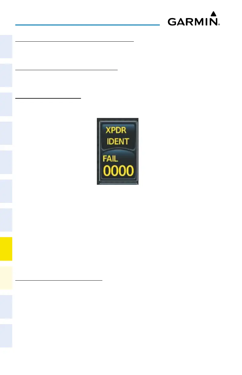
TRANSPONDER FAILURE
If the active transponder fails, green indications turn to yellow and the word FAIL is dis-
played on the Transponder Code/Mode Button.
Transponder Fail Indication
FMS DEGRADATION
The FMS will operate in either the GPS or the DR position fixing mode, depending on the
available sensors. If enabled and available for use, GPS1/GPS2 will have priority, and SBAS
will be used if available. If one GPS sensor fails, the system will automatically transition to the
other GPS sensor.
If GPS is lost and the system is unable to recover a signal, or if both GPS sensors fail, the
"GPS LOI" (Loss of Integrity) annunciation is displayed in amber on the PFW. Also, a system
message concerning the loss of GPS will appear on the Touchscreen Controller.
DEAD RECKONING NAVIGATION
The system will revert to Dead Reckoning (DR) mode if the system is no longer fully using
any GPS sensor for position fixing, even if airspeed and heading data are unavailable. In DR
Mode, the system will use its last-known position combined with continuously updated air-
speed and heading data (when available) to calculate and display the aircraft’s current estimat-
ed position. It is important to note that estimated navigation data supplied by the system in DR
mode will become increasingly unreliable and must not be used as a sole means of navigation.
DR mode will be indicated on the system by the appearance of the letters “DR” displayed in
amber on the HSI, and on top of the aircraft symbol on map displays. The CDI deviation bar
will be displayed in amber, and the "UNABLE RNP" annunciation will also be displayed on the