Cockpit Reference Guide for the Cirrus SR2x with Perspective Touch+ by Garmin
190-02954-01 Rev. A
18
Engine & Airframe Systems
Flight
InstrumentsEIS
Nav/Com/
XPDR/Audio
Flight
Management
Hazard
AvoidanceAFCS
Additional
FeaturesAnnun/AlertsAppendixIndex
Flight
InstrumentsEAS
Audio and
CNS
Flight
Management
Hazard
AvoidanceAFCS
Additional
Features
Abnormal
OperationAnnun/AlertsAppendixIndex
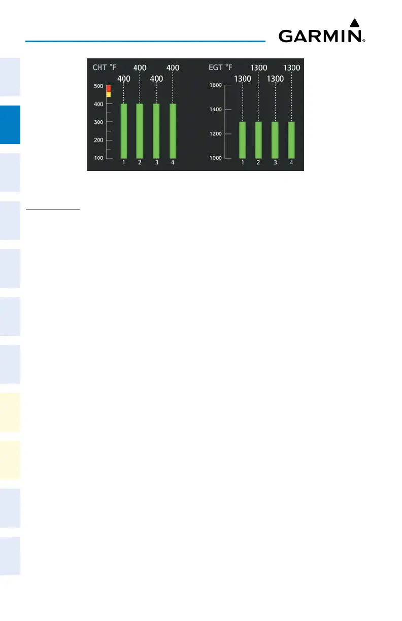
SR20 CHT/EGT
ELECTRICAL
The ‘Electrical Synoptic’ Page uses a simplified diagram of the aircraft’s electrical system to
display the system status. When the electrical system is operating normally, all objects and
lines are shown in green or white on the system diagram. Lines between objects represent
electrical connections. Green lines indicate there is current flow. White lines indicate there is
no current flow. Objects in green are active. Objects in white are inactive. Amber objects, text/
background, or lines indicates an abnormal or caution state. Red objects or text/background
indicates a warning state.
Accessing the Electrical Synoptics:
From MFW Home, touch Aircraft Systems > Electrical Power.