GE MEDICAL SYSTEMS
D
IRECTION 2392751-100, REVISION 3VIVID™ 4 SERVICE MANUAL
Chapter 5 - Components and Function (Theory) 5-17
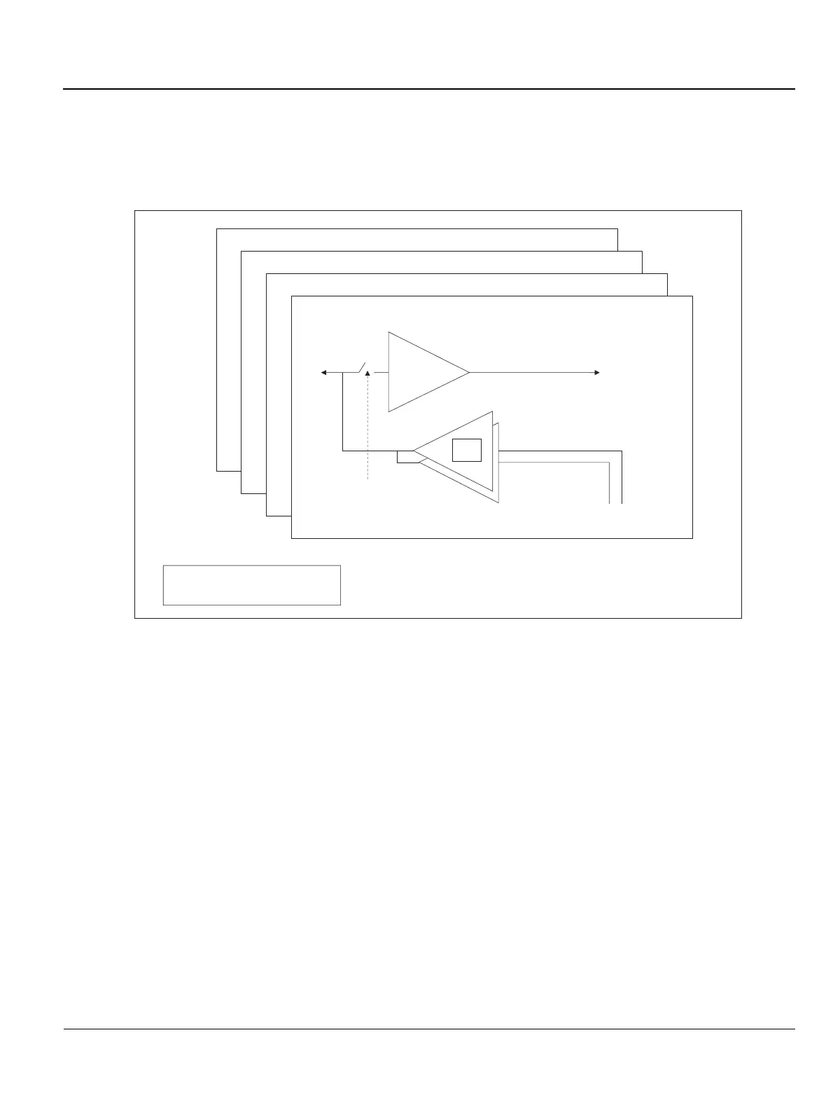
5-4-2-2 TR4 Board Description
The TR4 Board has four transmit and receive signal channels. Each channel has two pulsars for
different transmitted Tx voltages, and a low-signal receiver amplifier. Both are connected to the same
input/output line. The receiver is buffered from the transmitted voltage (up to 80V) by an electronic
switch to avoid high voltage on the receiver input.
Figure 5-11 TR4 Board Block Diagram
TR4 Transmit Receive X4 Board
Rx
BF Channel
Probe
CTRL
0-40V
0-80V
Tx
Tx Voltage
 Loading...


