GE MEDICAL SYSTEMS
D
IRECTION 2392751-100, REVISION 3VIVID™ 4 SERVICE MANUAL
8-94 Section 8-6 - Lower Section Components Replacement
8-6-6 Swivel Release Cable Replacement Procedure
NOTE: This section describes the installation and removal procedures for the Swivel Release Cable
(Part No. 2392103) only. For instructions on replacing the Gas Spring Cable, refer to the Gas Spring
Cable Removal Procedure on page 8 - 89.
Use the appropriate flat and Phillips-type screw drivers, Allen key, wire cutter and the appropriate
open-wring wrenches as indicated in the swivel release cable replacement procedure.
8-6-6-1 Preparation
Shut down the Vivid™ 4 ultrasound unit, as described in Chapter 3 - Installation.
8-6-6-2 Swivel Release Cable Removal Procedure
1) Raise the control console to its maximum height.
2) Remove the control console lower rear cover, as described in the Control Console Lower Rear
Cover Removal Procedure on page 8 - 19.
3) Remove the control console lower cover, as described in the Control Console Lower Cover
Removal Procedure on page 8 - 18.
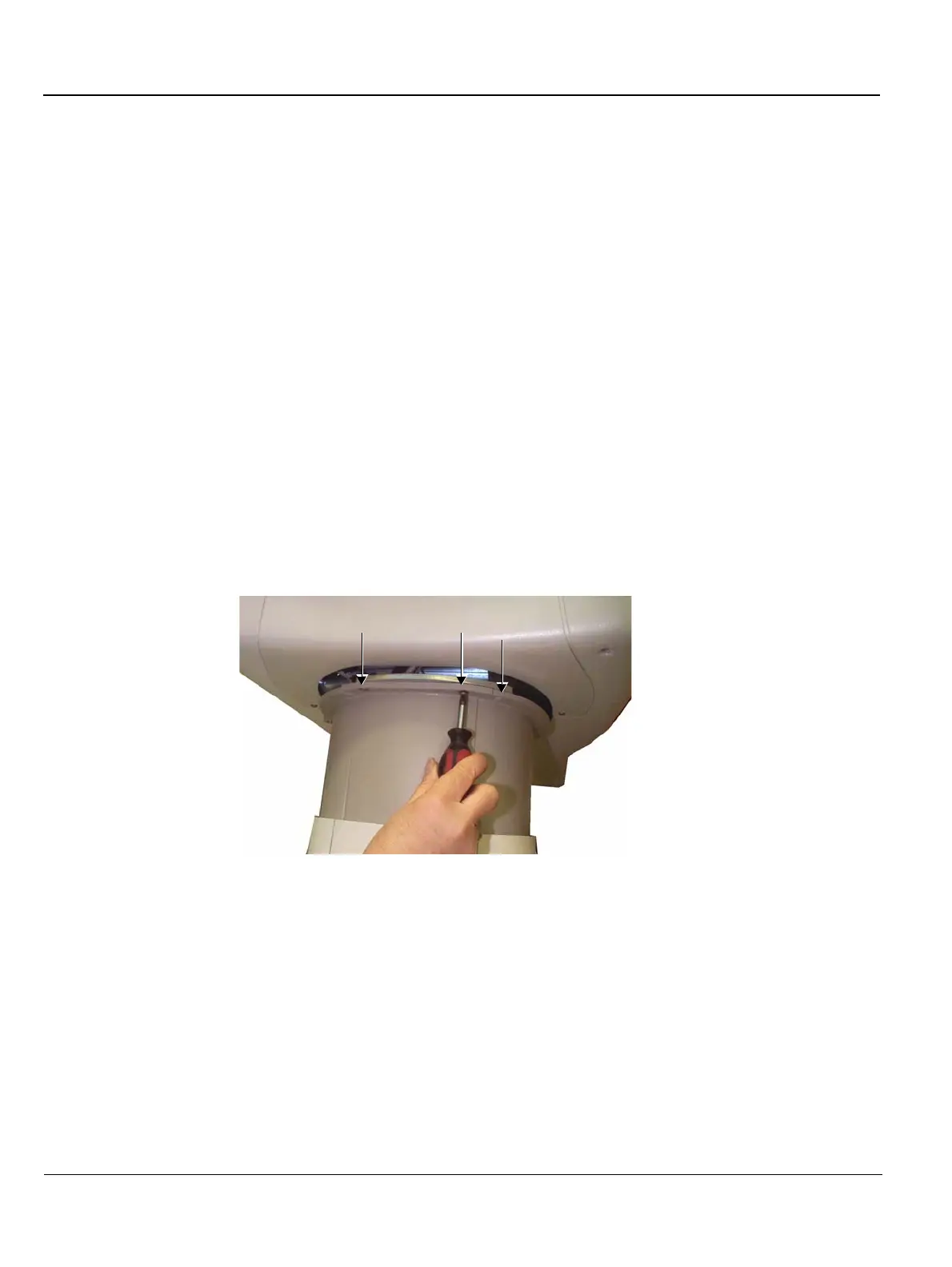
4) Loosen the three screws securing the gas spring cover central sleeve in position (see Figure 8-76
below) and lower it downwards until it is resting in the collar of the top cover. (It is not necessary to
remove the sleeve completely).
Figure 8-76 Gas Spring Cover Central Sleeve
5) Remove the control console upper cover front, as described in the Control Console Upper Cover
(Front) Removal Procedure on page 8 - 14.
6) Remove the keyboard, as described in the Keyboard Removal Procedure on page 8 - 26.
7) Cut all the cable ties to free the swivel release cable.
NOTE: For clarification, the letters appearing in square brackets [ ] in the following steps correspond to the
letters shown in Figure 8-77 and Figure 8-78 below.
 Loading...


