GE MEDICAL SYSTEMS
D
IRECTION 2392751-100, REVISION 3VIVID™ 4 SERVICE MANUAL
Chapter 3 - Installation 3-25
3-5-2-1-1 Right Rear Panel Connectors
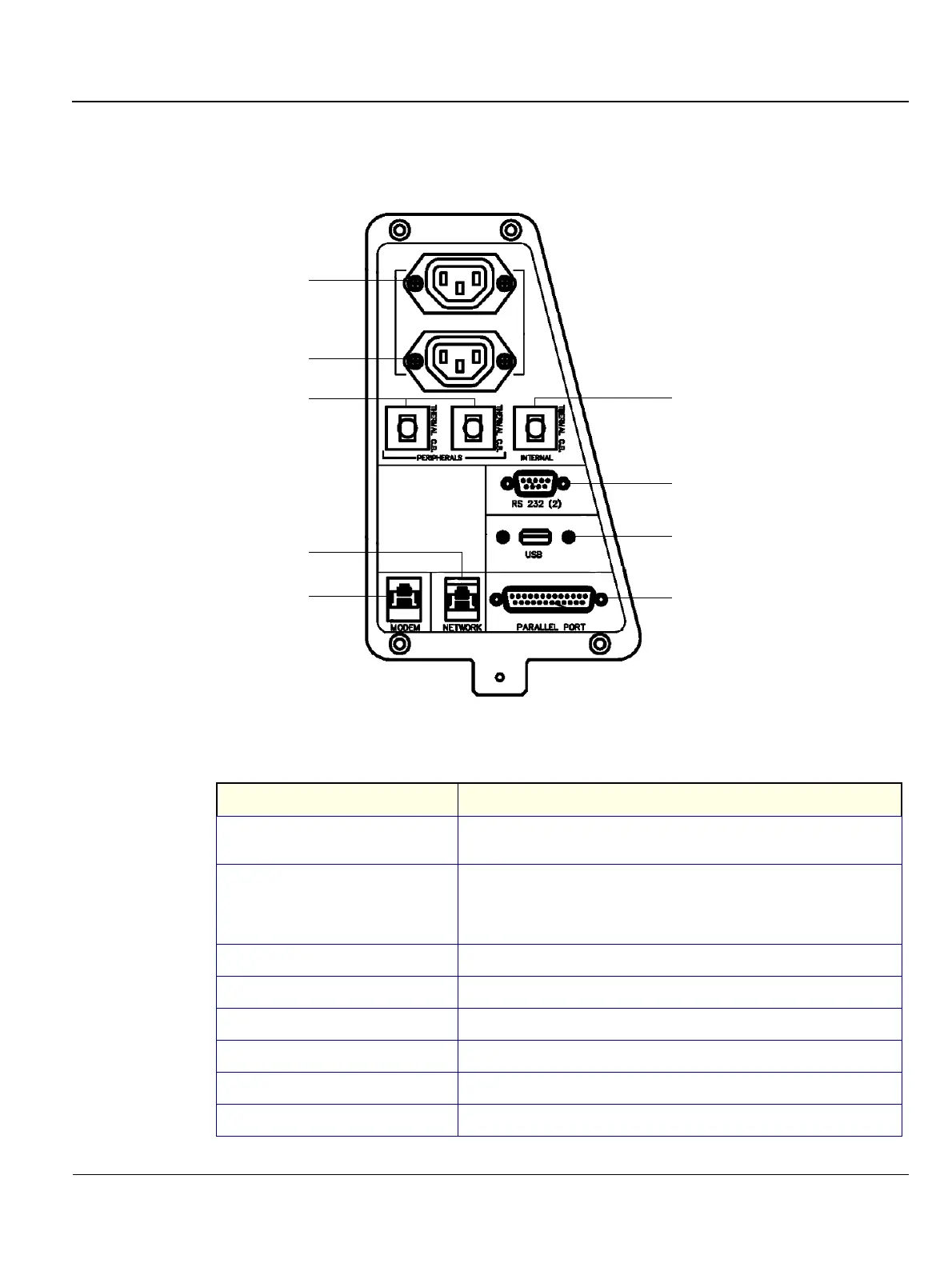
Table 3-9 describes the connectors included in the right rear panel (shown in Figure 3-16):
Figure 3-16 Right Rear Panel Connectors
Table 3-9 Right Rear Panel Connectors
Name Description
1. AUXILIARY AC OUTLET
For use with external peripherals. Voltages are set according to local country
voltage.
2. AUXILIARY AC OUTLET
For use with external peripherals. Voltages are set according to local country
voltage. If additional auxiliary outlets are required, use the special cable
provided by GE. DO NOT attempt to connect additional peripherals using an
external wall outlet.
3. THERMAL CIRCUIT BREAKERS Three 4A thermal circuit breakers for fuse protection.
4. NETWORK For the network connection.
5. MODEM For use with the service platform (iLinq).
6. RS 232 (2) Not in use.
7. USB For GE Service usage only (not for external USB devices).
8. PARALLEL PORT 25 pin connector for use with the external peripherals.
1
2
3
3
6
4
7
5
8
 Loading...


