IP8820/IP8830/IP8840
Installer Guide
6
2. Installing the IP8820/IP8830/IP8840
2.1 Connecting the IP Phone
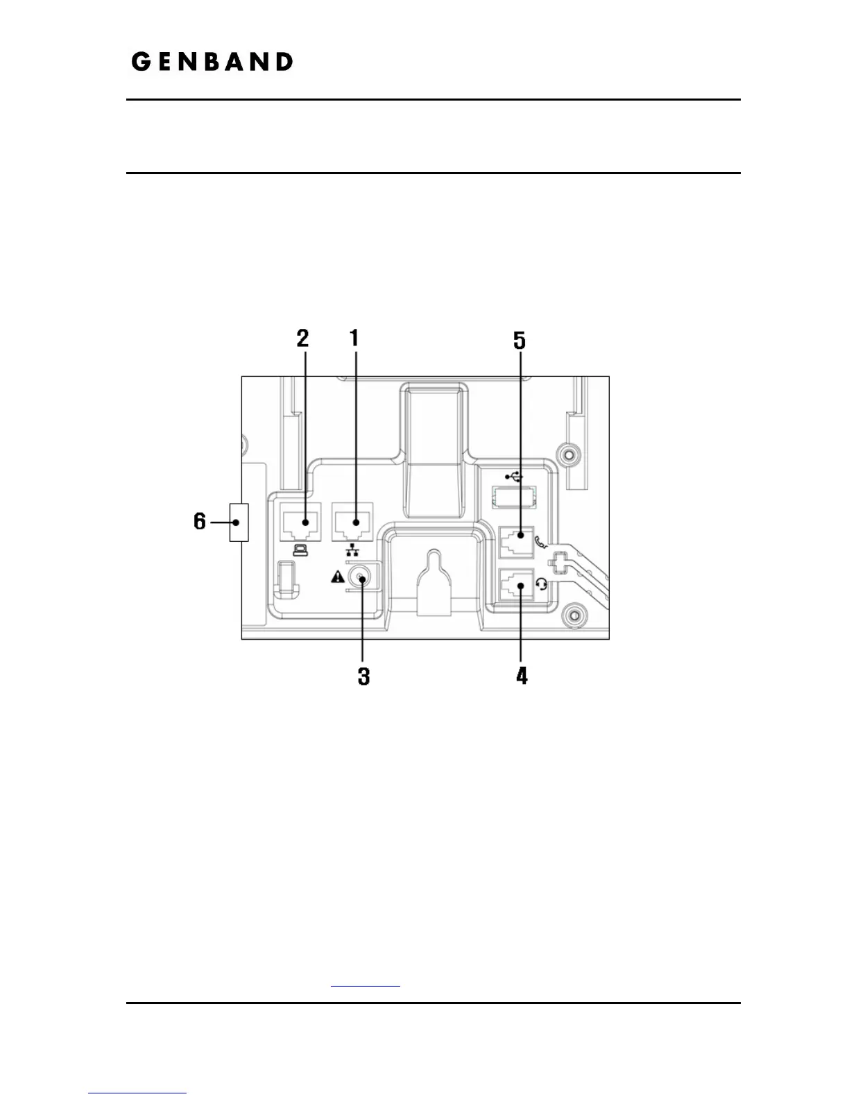
The figure below shows the cable connections for your IP Phone. The LAN and desktop PC
connections employ standard Category 5 cables terminated with RJ-45 connectors. The IP8800
series phones support PoE (Power over Ethernet) in accordance with the IEEE-802.1af
standard. When connected to a PoE complaint LAN port, the IP Phone derives power from the
port. If the LAN port does not support PoE, use the AC/DC adaptor, available separately, for
connection to power. The handset connects to the base with the supplied standard handset
coiled cord. Use the chart below to make connections to the IP Phone.
Figure 2.1-1 IP Phone Connections
Wiring Chart
1 LAN Connect the IP Phone LAN port to the LAN wall jack with the provided LAN
cable.
2 PC Connect the IP Phone PC port to your desktop PC with an RJ-45 terminated
UTP-5 cable.
3 Power If the LAN port supports PoE, IEEE 802.3af compliant, Class 2, the AC/DC
adapter is not required. If not supported, connect the IP Phone power port to
the DC out of Power Adapter. Connect the Power Adapter AC plug to an AC
wall jack.
4 Headset Connect Headset RJ-11 jack to the IP Phone headset jack.
5 Handset Connect the Handset coiled cord to the IP Phone base and handset.
6 Exp
Module
Connect cable, provided with the Expansion Module, to IP Phone before power
is applied, see section 2.3
.