IP8820/IP8830/IP8840
Installer Guide
7
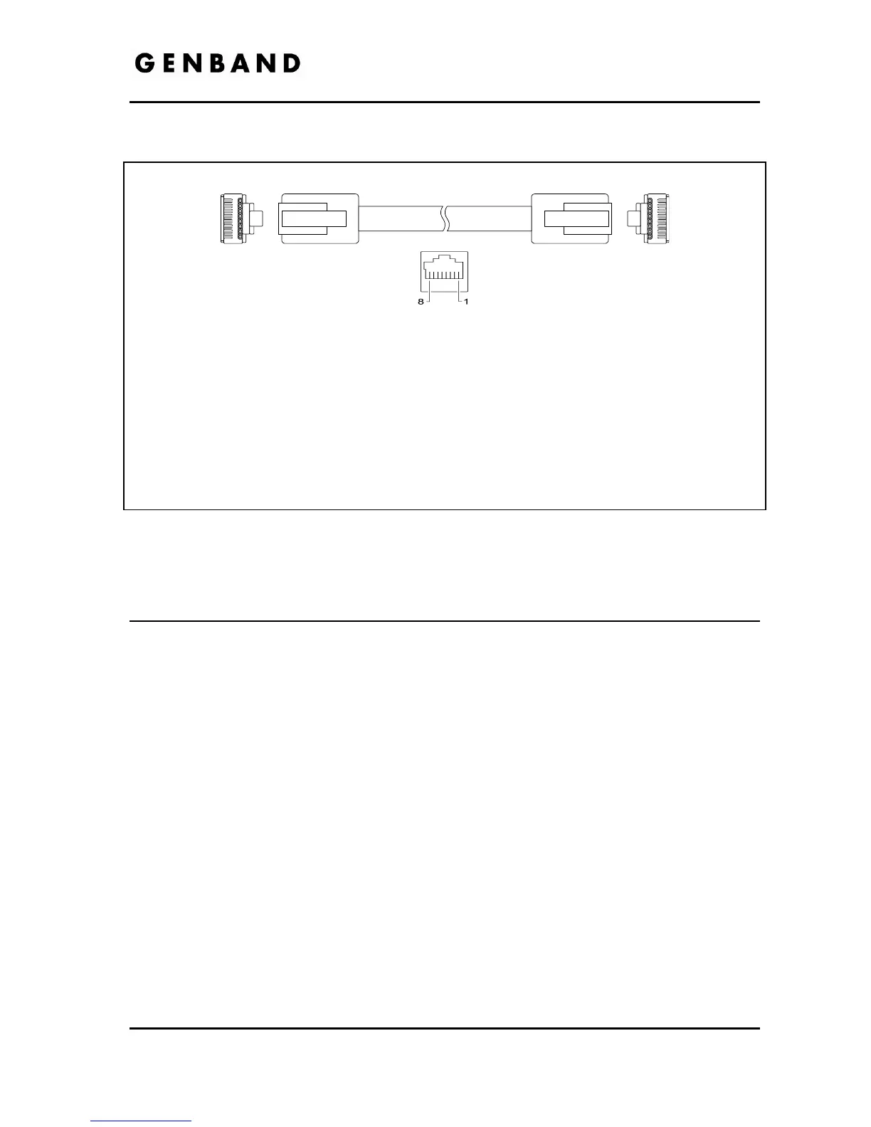
RJ-45 Pin Assignments
LAN port PC port
Pin 1 = TX+ Pin 1 = RX+
Pin 2 = TX- Pin 2 = RX-
Pin 3 = RX+ Pin 3 = TX+
Pin 4 = optional: 48V (or GND) Pin 4 = No connection
Pin 5 = optional: 48V (or GND) Pin 5 = No connection
Pin 6 = RX- Pin 6 = TX-
Pin 7 = optional: GND (or 48V) Pin 7 = No connection
Pin 8 = optional: GND (or 48V) Pin 8 = No connection
Figure 2.1-22.1-3 RJ-45 Terminations
2.2 Attaching the Foot Stand
The IP Phone is designed to use a Foot Stand to set the angle of the face of the phone. The
Foot Stand can be installed at an angle of about 30
o
or 55
o
based on the orientation of the Foot
Stand. The Foot Stand is attached to the base of the IP Phone as shown in Figure 2.2-1.
To attach th
e Foot Stand,
Align the tabs on the Foot Stand with the notches in the base of the IP Phone.
Push on the Foot Stand upward until it clicks indicating it is fully engage.