3-56
Chapter 3 Settings and Measurement
Contents General Description
Checks and Preparation
Settings and Measurement
Example of Use Specification
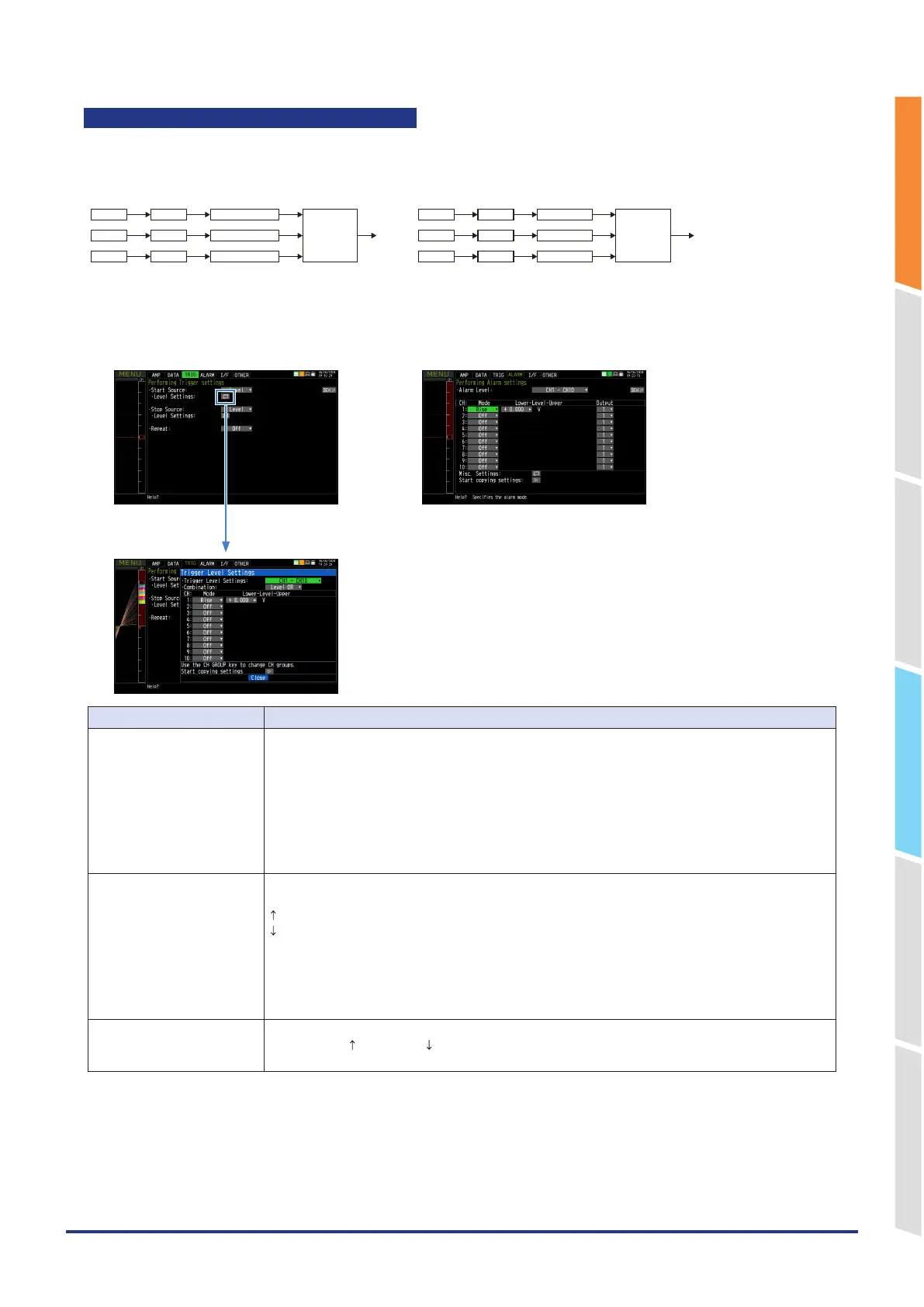
Trigger level settings/Alarm level settings
Specifies detailed conditions for each channel when the start and stop side source settings are Level.
The configuration of the level trigger is shown in the figure below.
<For trigger> <For alarm>
* Pulse and Logic are switchable.
CH n
Mode Level
Combination
Pulse n
Mode Level
Level
Trigger
Logic n
Mode
* Pulse and Logic are switchable.
* Specify an alarm output destination for each channel and Pulse/Logic.
Each of the alarms is ORed at the output destination.
Example: If you specify 1 as the output destination of 1CH and 2CH and 2 as that of 3CH
and 4CH, Alarm Output 1 occurs when one of 1CH and 2CH meets the conditions,
and Alarm Output 2 occurs when one of 3Ch and 4CH meets the conditions.
CH n
Mode Level
OR
Pulse n
Mode Level Alarm output n
Logic n
Mode Level
Place the cursor here and
press the [ENTER] key to open
the following setting screen.
<Trigger level settings> <Alarm level settings>
Select items Description
Combination
(For Trigger)
Sets a combination of trigger conditions for each channel.
Level OR: Starts (stops) capturing data when at least one of the specified trigger conditions is met.
Each condition is a Level operation.
Level AND: Starts (stops) capturing data when all of the specified trigger conditions are met.
Each condition is a Level operation.
Edge OR: Starts (stops) capturing data when at least one of the specified trigger conditions is met.
Each condition is Edge operation.
Edge AND: Starts (stops) capturing data when all of the specified trigger conditions are met.
Each condition is Edge operation.
Mode Sets a trigger comparison mode for each channel.
Off: Disables triggers for the setting channel.
H (rising): A trigger is generated when the input signal exceeds the specified level.
L (falling): A trigger is generated when the input signal falls below the specified level.
Win In: Used to specify the upper and lower limits for each channel.
When the input signal level is (or comes) between these limits, a trigger is generated.
Win Out: Used to specify the upper and lower limits for each channel.
When the input signal level is (or goes) out of these limits, a trigger is generated.
* There is no Window In setting and Window Out setting for logic CH.
Level Set the level for comparing triggers and alarms.
If the mode is H (rising) or L (falling), set one comparison level.
If the mode is Win In or Win Out, set two comparison levels.