2-5
CHAPTER 2 Checks and Preparation
Contents General Description
Checks and Preparation
Settings and Measurement
Example of Use Specification
2.4
Mounting the Extension Terminal Base (Optional) and
Extension Terminal Cable (Optional)
2.4.1 Mounting the extension terminal base
This section describes how to mount the extension terminal base.
When mounting the extension terminal base on the GL860, please make sure that the GL860’s power is turned OFF.
CAUTION
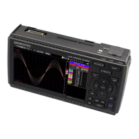
Prepare the extension terminal base and the extension terminal connection cable which are sold as optional items.
B-566 Extension Terminal Base
Extension terminal base: 1 unit Connection plate: 1 pc. M4 x 6 flat-head screw: 4 pcs.
B-567 Extension terminal connection cable (Select from two types of cables)
Extension terminal connection cable
(50 cm: B-567-05): 1 pc.
Extension terminal connection cable
(2 m: B-567-20): 1 pc.
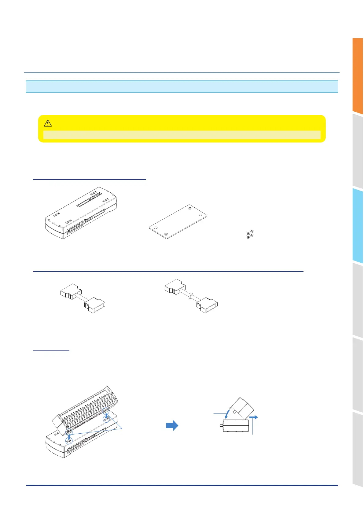
Mounting
1. Remove the Standard terminal or the Withstand high-voltage high-precision terminal mounted on the GL860.
2. Insert the lock tabs at the top of the terminal into the slots of the extension terminal base, and press the terminal until
the lock tabs at the bottom of the terminal are securely locked.
Insert
Press
* When installing the Withstand high-precision terminal
(B-565), please push it while pulling to the front.