2-7
CHAPTER 2 Checks and Preparation
Contents General Description
Checks and Preparation
Settings and Measurement
Example of Use Specification
2.4.2 Mounting multiple extension terminals
The mounting procedure of the multiple extension terminal set is described.
Mounting multiple extension terminals make sure the GL860’s power is OFF when mounting the extension terminals on the
GL860.
CAUTION
Prepare the sold separately extension terminal base and extension terminal connection cable.
B-566 Extension terminal base
Prepare the number of extension terminal bases that are equal to the number that the standard terminal or the
Withstand high-voltage high-precision terminal is added.
B-567 Extension terminal connection cable (Select from two types of cables)
Prepare one of the two types of extension terminal connection cables (50 cm: B-567-05 or 2 m: B-567-20).
Also, when you want to connect away between the extension terminal bases, the required number of the extension
terminal bases must be prepared.
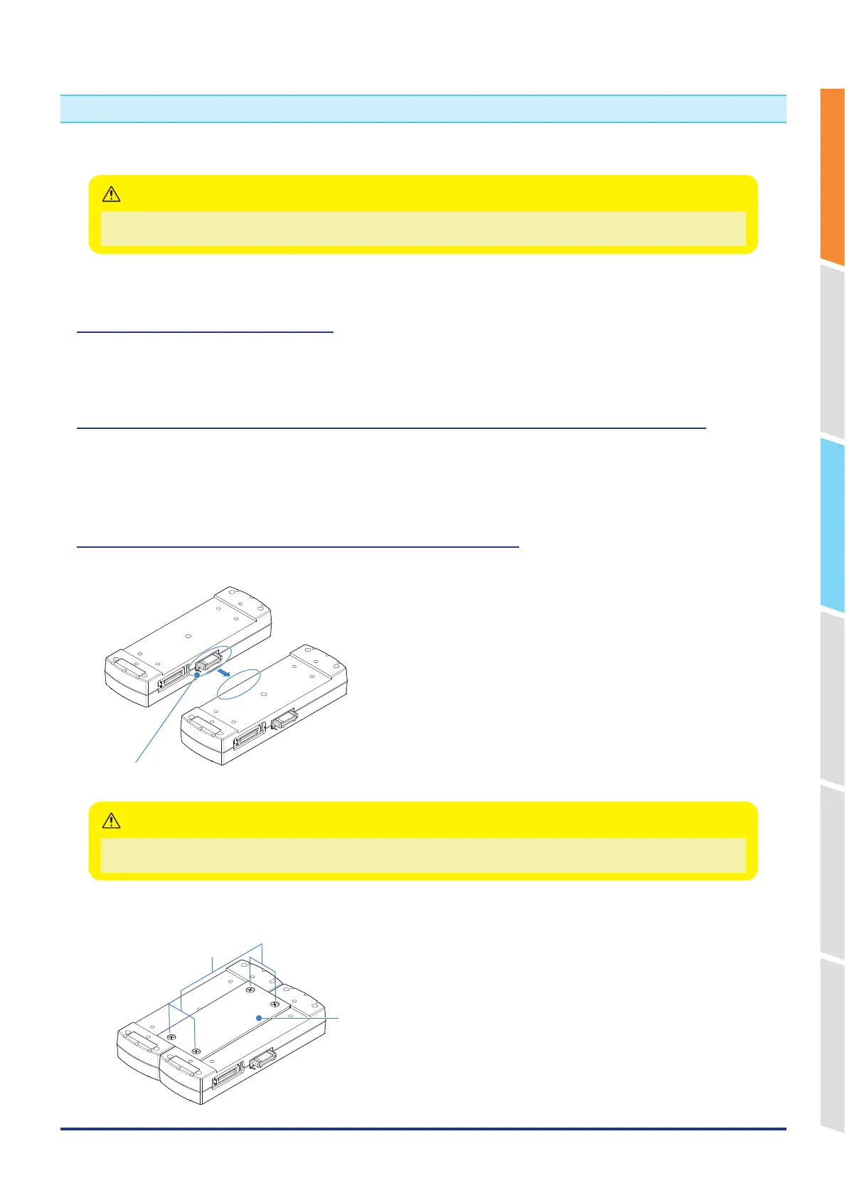
When direct-connecting the extension terminal bases
1. Connect the extension terminal base unit connectors as shown below.
* Please direct-connect to the protruding parts carefully.
• Please direct-connect the extension terminal bases carefully so as not to bend the protruding parts next to the connector.
• Please handle the connection plate in a horizontal state Until the connection plate is fixed.
CAUTION
2. Fix the connection plate using attached screws.
* Recommended screw torque: 14 kgf/cm
Connection plate
M4 x 6 flat head screws