65 / 116
S1002.PRO_mz12PRO_Teil2_V1sh
8. Use the lower selection key to change to the "Offs" line, if desired.
Instead of "SYM" and "ASY" at the lower edge of the display,
"STO" and "SEL" are shown.
Pressing the ENT key while the (inverse) "STO" field is active
("Store" or "Save") saves the current control position as an
offset position.
If, on the other hand, you switch to the "SEL" field with the
right selection key and then press the ENT key, the inverse rep-
resentation changes from the "SEL" field to the "Offs" line:
9. You can now either set an arbitrary offset value between ±150%
with the selection buttons, or by pressing the left and right selec-
tion buttons simultaneously, a changed value can be reset to the
default value.
10. Press the ENT key to complete the operation.
11. Press the ESC button to close the setting page and return to the
mixer list.
12. Proceed in the same way with the remaining mixers.
Curve mixer C6 ... C9 programming step-by-step
1. As described above under "Programming linear M1 ... 5 step-by-
step", select the required mixer and switch to its setting page.
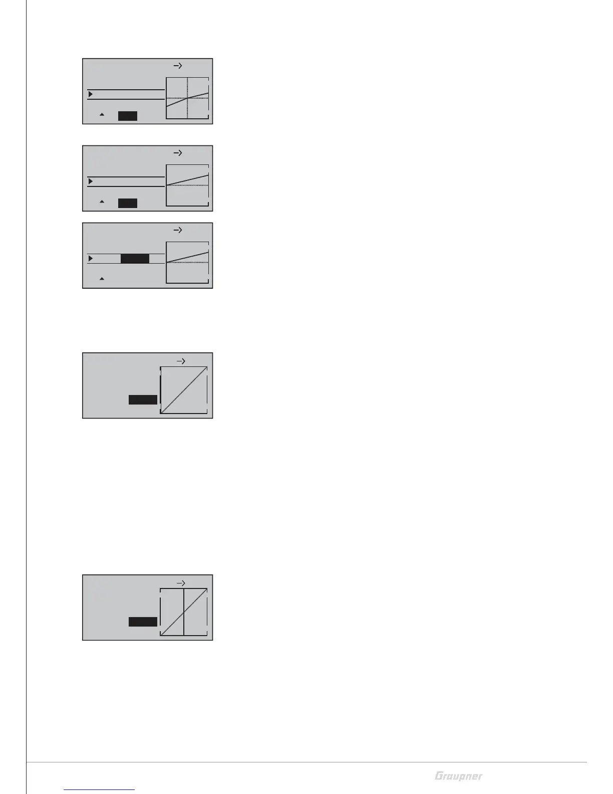
There is a vertical line in the graphic. This line represents the
current position of the control element at the mixer input. (In
the figure on the left, the line is located at the left edge of the
graphic as the CH1 stick is located at the idle stop.)
The dotted, oblique, line visualizes the characteristic of the
mixer, which is still linear at the moment.
In the line "Point", the number of the currently activated point
as well as its status "deactivated" or alternatively its setting
value in percentage control travel is displayed.
Between the two endpoints, "point1" at -100% and "point5"
at +100% of the control travel, up to three additional points
can be defined at -50%, 0% and +50% of the control travel.
2. Move the solid vertical line with the corresponding control ele-
ment to the point to be set.
3. Use one of the selection buttons to set the desired value or acti-
vate the point and then set the value. Alternatively, by pressing
the left and right selection buttons simultaneously, you can reset
a changed value to the default value.
4. Proceed in the same way with the remaining points.
L.MIX1
+50% +30%
0%
Os
SEL
STO
S1
Tr v
EL
L.MIX1
+50% +30%
–100%
Os
SEL
STO
C1
Tr v
EL
L.MIX1
+50% +30%
Os
SELSTO
C1
Tr v
EL
–100%
–100%
–100%
Input
Output
Point3
C.MIX6
normal
1
3
–100%
0%
0%
Input
Output
Point3
C.MIX6
normal
1
3
deact

 Loading...