GEN7iB
168
INTERFACE/CONTROLLER
INTERFACE/CONTROLLER
11
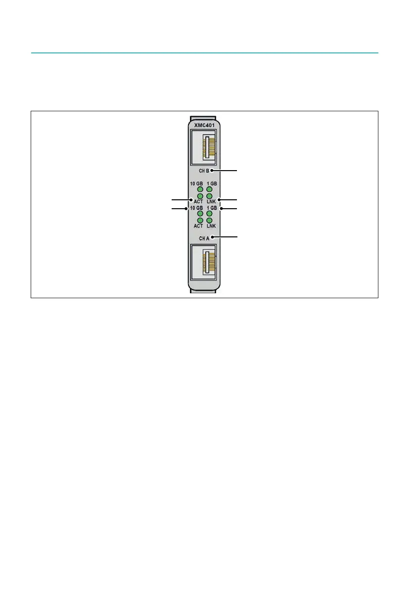
Front panel layout
The front panel of the10 Gbit Ethernet option has the following layout:
(
Fig. 11.18 Front panel of XMC401 10 Gbit Ethernet card
A CH B = NIC2 (Requires SFP+ module, not shown)
B ACT (green): Ethernet Activity (on when active)
C LNK (green): Ethernet Link (on when active)
D 10 Gbit (green): Ethernet Speed 10 Gigabit (always on)
E 1 Gbit (green): Ethernet Speed 1 Gigabit (always on
F CH A = NIC1 (Requires SFP+ module, not shown)
Fig. 11.18 shows the two interfaces of this option without installed SFP+ option, for
further details on the SFP+ options please see the next section.
Once the SFP+ option is installed in the 10 Gbit Ethernet interface, an LC optical cable
can be connected.

 Loading...