3 Piping work and refrigerant charge
Refrigerant and drain hose installation
SMGB0099 rev.0 - 12/2016
113
3
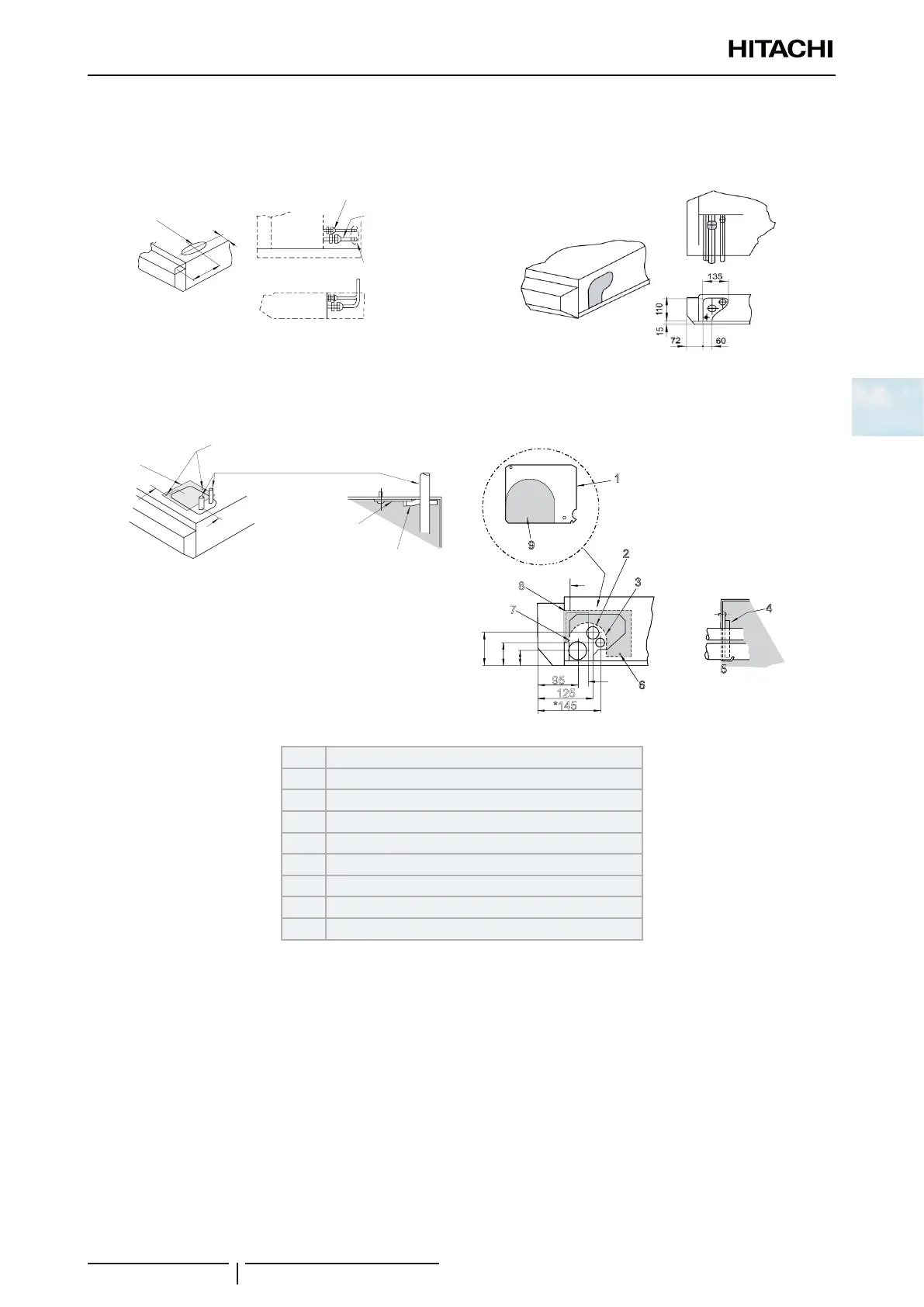
4 Remove the die-cut panel from the required part of the unit to install the refrigerant pipes.
a. Upper side.
Open the Knock-out hole
b. Rear side.
50
155
Open the die-cut panel
Liquid pipe
Gas pipe
Liquid pipe
Gas pipe
Open the die-cut panel
5 Install the pipes through it and seal them using the insulation supplied, as indicated below.
a. Upper side. b. Rear side.
A
Sealing
plate
M4 screws
B
Refrigerant pipe
Sealing plate
Seal with insulation Section A - B
P
1
2
3
4
5
6
7
8
9
P
1
2
3
4
5
6
9
125
*145
54
83
38
95
1 Sealing plate supplied (0.8x118x142 mm)
2 Gas refrigerant pipe
3 Liquid refrigerant pipe
4 Seal with insulation
5 Section P.P.
6 M4 screw
7 Sealing plate
8 M4 screw
9 Knock-out hole

 Loading...


