4 Electrical and control settings
Unit electrical wiring and connection
SMGB0099 rev.0 - 12/2016
134
4.1.3 Transmission wiring between outdoor and indoor unit
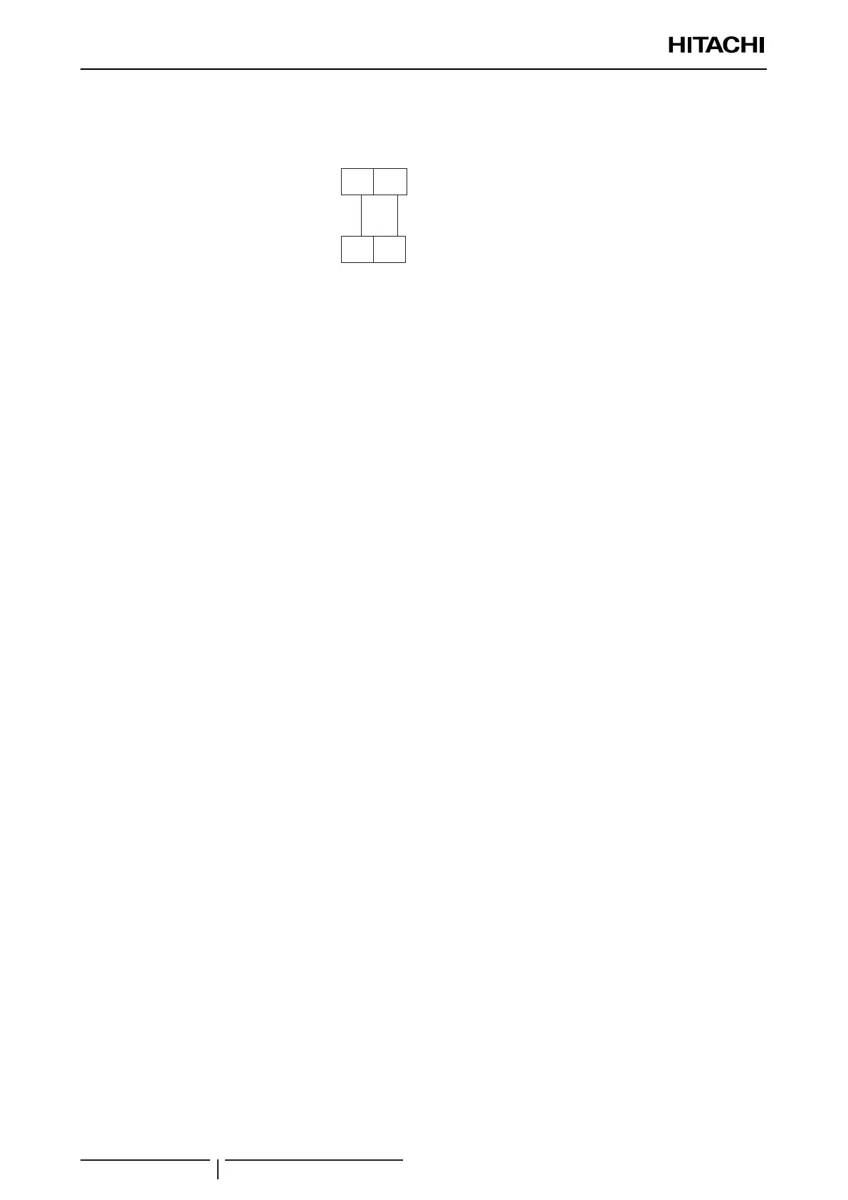
• The transmission is wired to terminals 1-2.
• The H-LINK II wiring system requires only two transmission cables that connect the indoor unit and the outdoor unit.
1
1
2
2
Indoor unit
Outdoor unit
• Use twist pair wires (0.75 mm²) for operation wiring between outdoor unit and indoor unit. The wiring must consist of
2-core wires (Do not use wire with more than 3 cores).
• Use shielded wires for intermediate wiring to protect the units from noise interference, with a length of less than 300m
and a size in compliance with local codes.
• In the event that a conduit tube for eld-wiring is not used, x rubber bushes to the panel with adhesive.
! CAUTION
Ensure that the transmission wiring is not wrongly connected to any live part that could be damaged the PCB.
4.1.4 Electrical connection of RCI units
Work prior to the electrical connection
1 Turn off the power supply switches before starting work and t the appropriate locks and safety warnings.
2 Wait 5 minutes after turning off the power supply switches.
3 Check that the fans on the indoor and outdoor units are at a standstill before starting work.
? NOTE
• The electrical power for the unit must involve a specic power line, with an exclusive power control switch and residual current breaker,
installed in line with local or national safety regulations.
• Check that the electrical power line has enough capacity to supply the unit. Its length, the cable diameter and their protection (sleeve
or jacket) must be appropriate for the unit.
• For further information, always consider the current regulations in the country where the unit is to be installed.
! CAUTION
• Risk of re: cables must never touch the refrigerant pipes, printed circuit boards (PCB), sharp edges or electrical components inside
the unit to avoid damaging them.
• Loose connection terminals may lead to cable and terminal overheating. The unit may operate incorrectly, leading to a risk of re.
Check that the cables are rmly secured to the connection terminals.
Electrical connection
Check that the power supply for the RCI indoor unit is 230 V. If not, replace the CN connectors on the TF transformers in
the electrical box.
Make the connection between the indoor unit and the air panel.
? NOTE
• To prevent the screws from falling from the terminal strip, do not remove them completely, hold onto the terminal and check that the
screw is secure through the hole.
• Use the following screws for the terminal strip:
- M4 screw for the power supply.
- M3.5 screw for the communication line.

 Loading...


