5 Control system
Printed circuit board for complementary systems
SMGB0099 rev.0 - 12/2016
196
5.9.2 Printed circuit board for DX-Interface
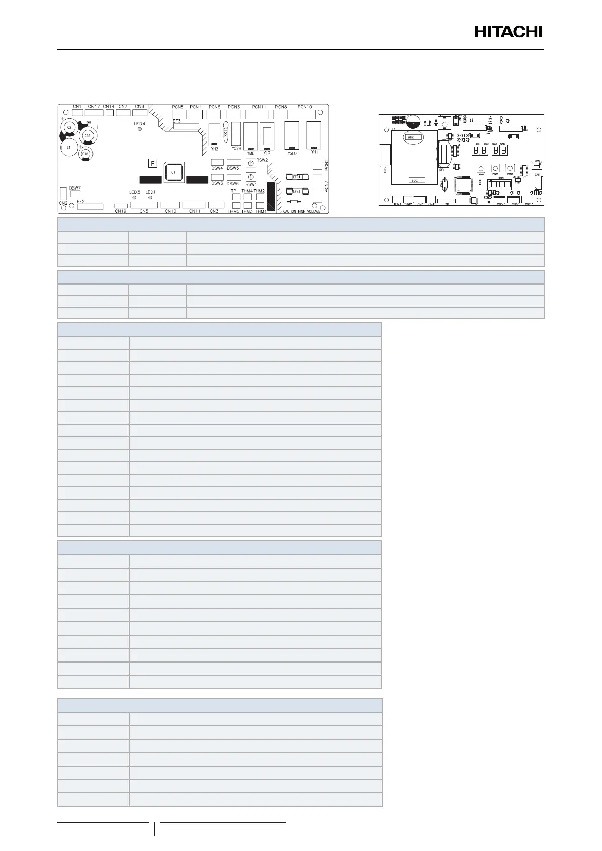
PCB1 sockets location
PCB2 sockets location
PCB1 LED indicator
LED1 Red This LED indicates the transmission status between the indoor unit and the remote control.
LED3 Yellow This LED indicates the transmission status between the indoor unit and the outdoor unit.
LED4 Green PCB power supply
PCB2 LED indicator
LED1 Yellow H-LINK transmission 1
LED2 Green PCB power supply
LED3 Yellow H-LINK transmission 2
PCB1 Connector indication
PCN1 230V transformer
PCN2 TB1
PCN6 TB1
PCN7 TB1 and PCB2
PCN10 TB1
PCN11 TB1
THM1 Coil inlet thermistor
THM2 Coil outlet thermistor
THM3 Liquid pipe thermistor
THM5 Gas pipe thermistor
CN1 Transformer
CN2 TB2 and PCB2
CN11 TB1
CN14 TB2
EFR1 PCB1 fuse
EFS1 PCB1 fuse
PCB2 Connector indication
PCN1 TB1 and PCB1
THM1 Optional air temperature sensing
THM2 Optional air temperature sensing
CN1 TB2 and PCB1
CN2 TB2
CN3 TB2
CN4 TB2
CN5 TB2
CN6 TB2
EF1 PCB2 fuse
Switch indication
DSW1 Optional functions
DSW2 End resistance
DSW3 Capacity code
DSW4 Unit model code
DSW5, RSW2 Refrigerant cycle number
DWS6, RSW1 Indoor unit number settings
DSW7 Fuse re-establishing

 Loading...


