5 Control system
Printed circuit board for RPC-FSN3
SMGB0099 rev.0 - 12/2016
190
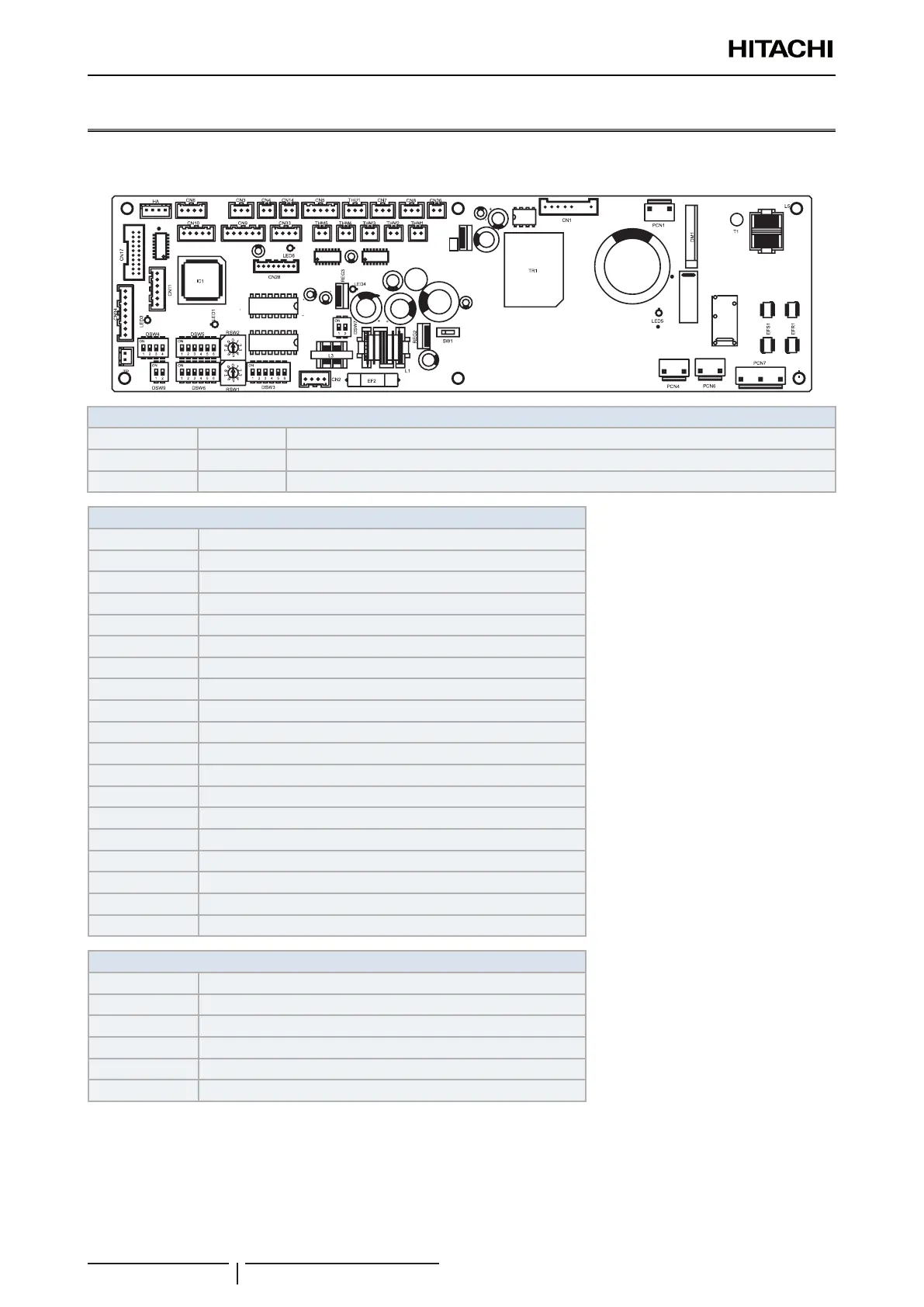
5.5 Printed circuit board for RPC-FSN3
The indoor unit PCB operates with four types of DIP switches, a slide switch and a rotary switch. The position is as
follows:
LED indicator
LED1 Red This LED indicates the transmission status between the indoor unit and the remote control.
LED3 Yellow This LED indicates the transmission status between the indoor unit and the outdoor unit.
LED4 Green PCB power supply
Connector indication
THM1 Air inlet thermistor
THM2 Air outlet thermistor
THM3 Freeze protection thermistor
THM5 Gas pipe thermistor
PCN7 Terminal board
CN1 Motor for indoor fan
CN2 Terminal board 2
CN3 Optional input functions
CN7 Optional output functions
CN8 Optional output functions
CN10 Motion Sensor Kit connection
CN11 Expansion valve control
CN14 Float switch
CN17 Swing louver motor
CN36 Power source for drain pump
EFS1 PCB2 fuse
EFR1 PCB2 fuse
EF1 PCB1 fuse
EF4 PCB1 fuse
Switch indication
SW1 Comunicaton type
DSW3 Capacity code
DSW4 Unit model code
DSW5, RSW2 Refrigerant cycle number
DWS6, RSW1 Indoor unit number settings
DSW7 Fuse re-establishing
 Loading...


