4 Electrical and control settings
Wiring diagrams for indoor units and complementary systems
SMGB0099 rev.0 - 12/2016
169
4
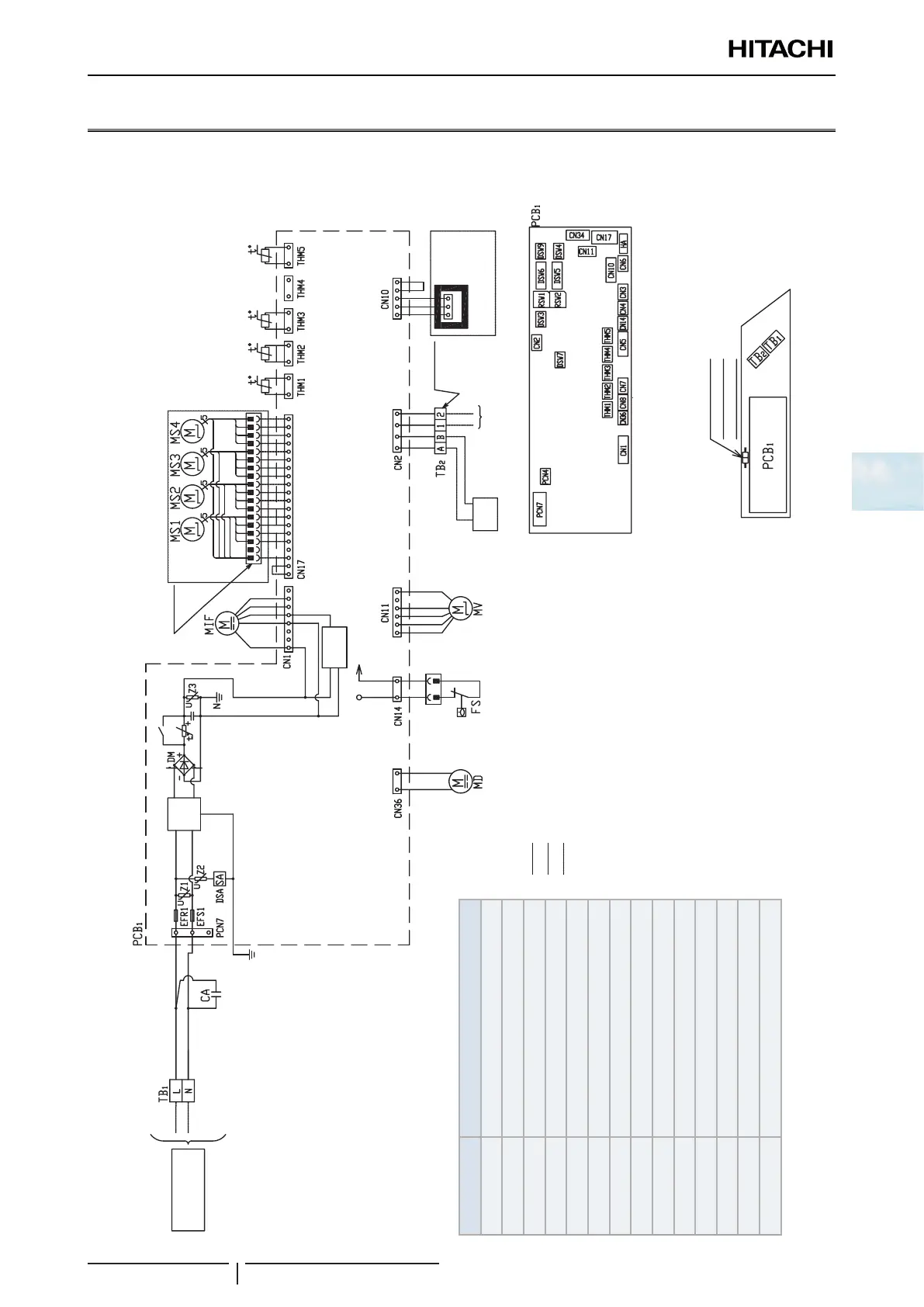
4.3 Wiring diagrams for indoor units and complementary systems
4.3.1 Wiring diagrams for indoor units
Wiring diagrams for the RCI-(1.0-6.0)FSN4 indoor units
1 ~ 230V 50 Hz
Noise
lter
◆
Field connection
Air panel
Supply
circuit
(Gas
pipping)
(Freeze
protection)
(Air
outlet)
(Air
inlet)
Remote
control switch
(PC-ARFPE)
Printed circuit board
Electrical control box of Indoor unit
Service connector for drain
discharge mechanism
Operation
line DC5V
◆
Field connection
◆
►
PCB for
motion sensor
Air Panel
Factory wiring
Earth wiring
Field wiring
Field connection
Optional parts
Mark Name
CA Capacitor
TB1, 2 Terminal board
PCB1 Printed circuit board
PCN4,7 Connector on PCB
CN1~36 Connector on PCB
RSW1, 2 Rotary switch
DSW3~9, SW1 Dip switch for settings
MV Micro-computer control expansion valve
MIF Motor for Indoor fan
MS Motor for automatic swing louver
MD Motor for drain discharge mechanism
FS Float switch
THM1~5 Thermistors
EFR1 Fuse

 Loading...


