4 Electrical and control settings
Setting of DIP switches and RSW switches
SMGB0099 rev.0 - 12/2016
161
4
• DX-Interface
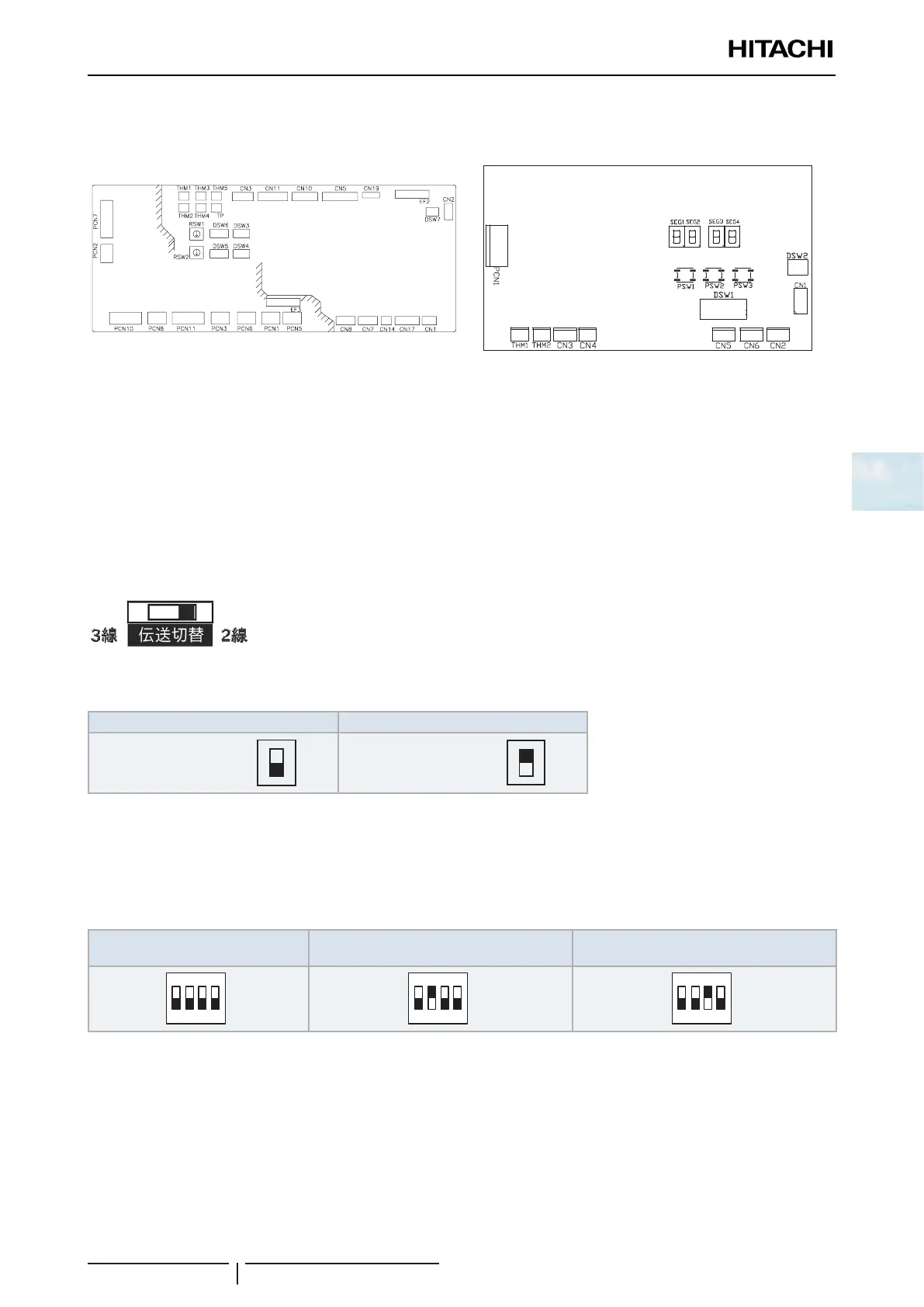
PCB1 PCB2
4.2.2 Functions of the DIP switches and RSW switches (Indoor units)
! CAUTION
Turn off the power supply before setting the DIP switches. If not, the settings will not be valid.
? NOTE
• The symbol “■” indicates the position of the DIP switches. The gures show the setting before transmission or after selection.
• If the “■” mark is not displayed, this indicates that the position of the pin is not affected.
SW1 (RCI-FSN4, RPC-FSN3 and RPK-FSN(H)3M only)
No settings are required. Factory setting:
SW2 (RPK-(0.6-4.0)FSN(H)3M only)
Factory setting Wired remote control
Wired Wired
Wireless Wireless
? NOTE
In case of using the wired remote control or receiver kit PC-ALHZF set the SW2 to “Wired”.
DSW2: optional function setting (RPK-FSN(H)3M only)
Factory setting Special lower capacity setting (0.6HP)
(1)
Distinguish of indoor units using
wireless remote control
(2)
? NOTE
•
(1)
Only available for RPK-0.8FSN3M unit. 0.8 HP Indoor Units set to a lower capacity (0.6 HP) can only be used in combination with
SET FREE MINI series 2 (RAS-(4-6)FS(V)N(Y)3E) and SET FREE FSXN series.
•
(2)
In order to identify one indoor unit with its own wireless remote control, set DSW2 pin3 ON and set the wireless remote control at
“b” mode. For more information, please refer to the corresponding Installation and Operation Manual.
• When using a wireless remote controller, no additional receivers are required for individual operation.
• For simultaneous operation it is required:
Option 1: PC-ARFPE remote control.
Option 2: In the case of wireless operation with PC-AWR, PC-ALHZF receiver kit is necessary.
In both options change SW2 to wired setting.

 Loading...


