9 Servicing
RPK-FSN(H)3M - Wall mounted
SMGB0099 rev.0 - 12/2016
313
9
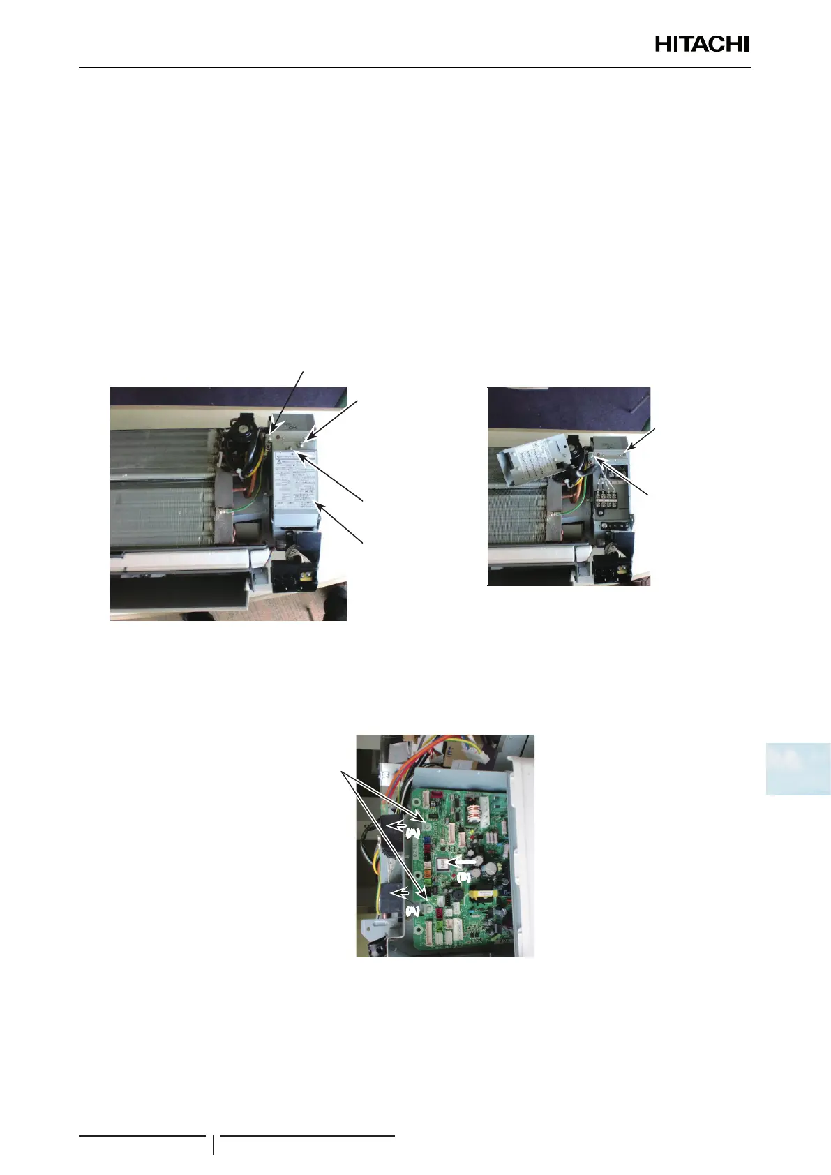
9.9.6 Replacing PCB1 for Control
For RPK-(0.6-1.5)FSN(H)3M
1 Remove the electrical box according to the “9.9.7 Removing Electrical Box” chapter.
? NOTE
If there is enough service space to the right side of the electrical box, PCB1 can be replaced without removing the electrical box.
2 Remove 1 screw xing the terminal board cover to remove it.
3 Remove 1 screw xing the electrical box cover located to the right side of the electrical box. Then remove the
electrical box cover.
4 Remove the wirings and connectors (on the PCB1) for the freeze protection thermistor, gas pipe thermistor, inlet air
thermistor, outlet air thermistor, transmission, remote control switch, power source, external input/output, auto-louver,
PCB for receiver (with indicator), fan motor and expansion valve coil.
Screw for electrical box cover
Screw for terminal
board cover
Screw for switch
cover
Electrical box
Electrical box cover
Screw for electrical
box cover
5 Remove 2 spacers in the direction of the arrow (A) and also remove PCB1 in the direction of the arrow (B).
6 After the replacement, attach them in the reverse procedure.
? NOTE
If the unit with the expansion valve kit is used, regard “expansion valve coil” as “expansion valve relay cord.”
(A)
(A)
(B)
Spacers
 Loading...


