9 Servicing
DX-Interface
SMGB0099 rev.0 - 12/2016
342
9.12 DX-Interface
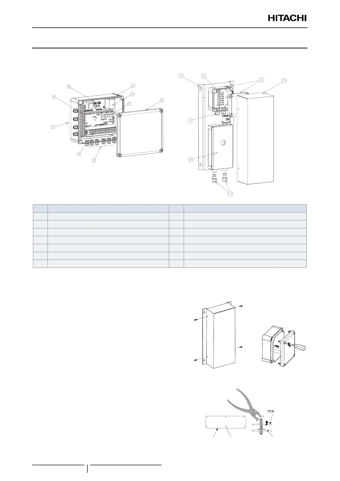
9.12.1 Structure and part names
DX-Interface EXV-(2.0-10.0)E2
Nº Name Nº Name
1 Control box 8 PCB2
2 Control box cover 9 Expansion valve box
3 Cable gland 10 Terminal board 3
4 Terminal board 1 11 Terminal board box and cover
5 PCB1 12 Expansion valve box cover
6 Terminal board 2 13 Refrigerant connections
7 Transformer 14 Expansion valve device
9.12.2 Removal of the electrical components
Control box
1 Remove the control box cover unscrewing the 4 screws.
Expansion valve box
1 Remove the expansion valve box cover unscrewing the 4
screws.
2 Remove the terminal box like the control box cover.
! CAUTION
Handle the support carefully to avoid damaging the electrical
components.
! CAUTION
• Do not touch the electrical components of the PCB.
• Do not apply force to the PCB, as this could damage it.
• Pay special attention to the position of the connectors on the PCB.
An incorrect position during installation may damage the PCB.
PCB
Holder Electrical box

 Loading...


