5 Control system
Printed circuit board for complementary systems
SMGB0099 rev.0 - 12/2016
195
5
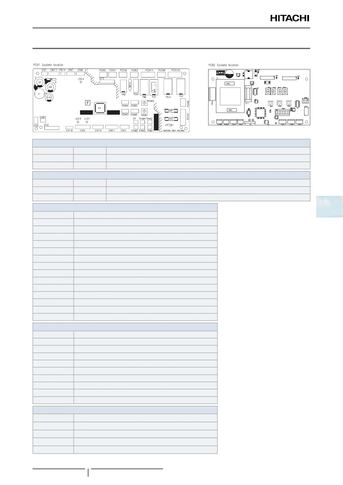
5.9 Printed circuit board for complementary systems
5.9.1 Printed circuit board for KPI
PCB1 LED indicator
LED1 Red
This LED indicates the transmission status between the indoor unit and the remote control.
LED3 Yellow
This LED indicates the transmission status between the indoor unit and the outdoor unit.
LED4 Green
PCB power supply
PCB2 LED indicator
LED1 Yellow H-LINK transmission 1
LED2 Green PCB power supply
LED3 Yellow H-LINK transmission 2
PCB1 Connector indication
PCN1 230V transformer
PCN3 Operation signal for electric heater installation
PCN7 TB1 and PCB2
PCN10 Damper
THM1 Air outlet thermistor
THM2 Air inlet thermistor
THM3 Liquid pipe thermistor
THM5 Gas pipe thermistor
CN1 Transformer
CN2 TB1 and PCB2
CN11 Expansion valve
CN14 Float switch
EFR1 PCB1 fuse
EFS1 PCB1 fuse
EF3 PCB1 fuse
PCB2 Connector indication
PCN1 TB1 and PCB1
THM1 Coil inlet thermistor
THM2 Coil outlet thermistor
CN1 TB1 and PCB1
CN2 CO2 sensor 4-20 mA
CN3 CO2 sensor 0-10 V
CN4 CO2 sensor ON/OFF
CN5 Motor for fan 1
CN6 Motor for fan 2
EF1 PCB2 fuse
Switch indication
DSW3 Capacity code
DSW4 Unit model code
DSW5, RSW2 Refrigerant cycle number
DWS6, RSW1 Indoor unit number settings
DSW7 Fuse re-establishing
 Loading...


