8 Electrical check of main parts
Thermistor
SMGB0099 rev.0 - 12/2016
240
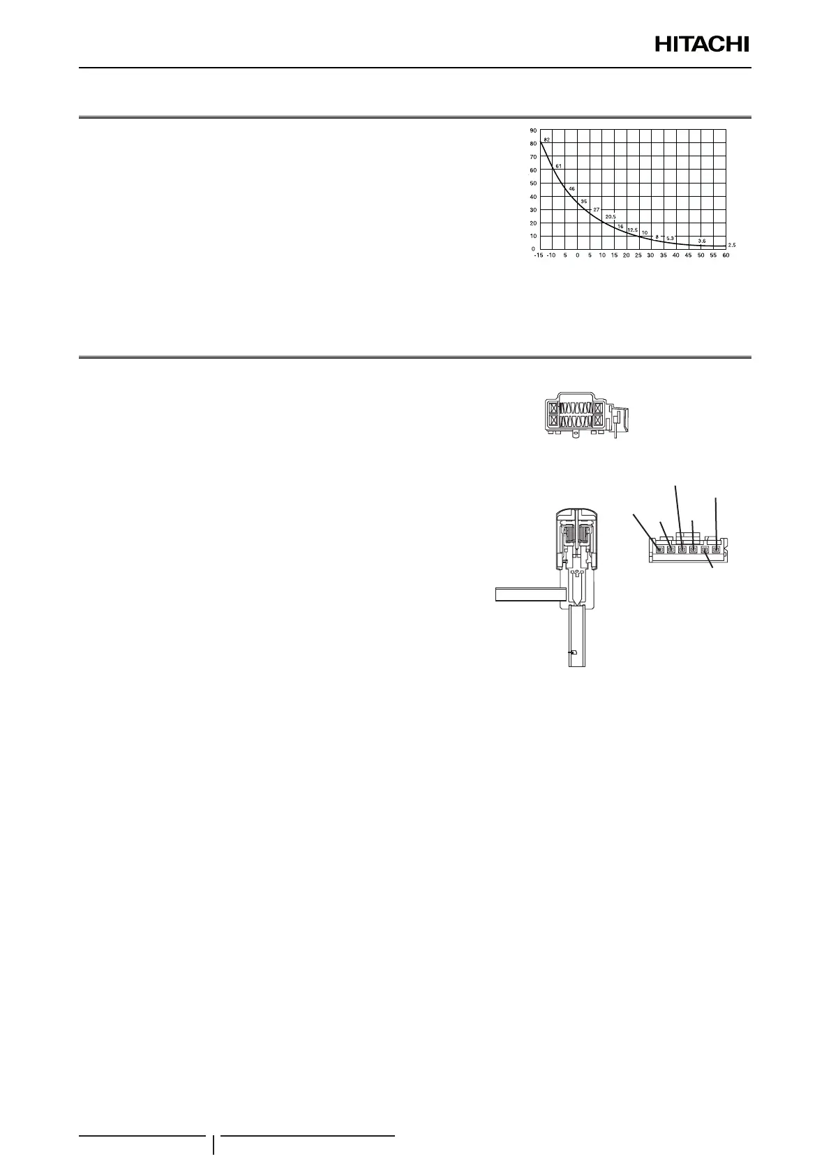
8.1 Thermistor
Check that the thermistors are connected to the PCB inlet and, if not,
connect them.
Use a multimeter to check that the thermistor resistances are
between 240 Ω and 840 kΩ. Otherwise, replace any defective
thermistors.
? NOTE
This gure is applicable to the following thermistors.
1. Inlet Air Thermistor (THM1), 2. Liquid Pipe Thermistor (Freeze Protection)
(THM3), 3. Gas Pipe Thermistor (THM5), 4. Outlet Air Thermistor (THM2)
Thermistor
resistance
(KΩ)
Air temperature (ºC)
Thermistor characteristics
8.2 Electronic expansion valve
1 Check that the voltage of the valve ranges between 12Vdc±1.2V.
2 Use a multimeter to check the coil resistance (per phase). This
ranges between 100 Ω±10% at an ambient temperature of 20°.
3 Check the number of pulses per second. This ranges between
100Ω ± 250 pulses per second (the width between pulses is
greater than 3 mm ) on activating phase 2.
4 Check that the valve ow is reversible.
5 When the valve is fully open and in heating process, check that
the temperature of the liquid in the piping increases. If not, this
indicates a fault.
6 When the valve is slightly open or fully open, check that the
temperature of the freeze protection thermistor is higher than the
suction temperature. If not, this indicates a fault.
Electronic
expansion valve coil
Electronic expansion
valve body
Electronic expansion
valve connector
(6)
Blue
(5)
Orange
(4)
Yellow
(3)
White
(1)
Red
(2)
Free

 Loading...


