2 Unit installation
RPF - Floor type, RPFI - Floor concealed type
SMGB0099 rev.0 - 12/2016
66
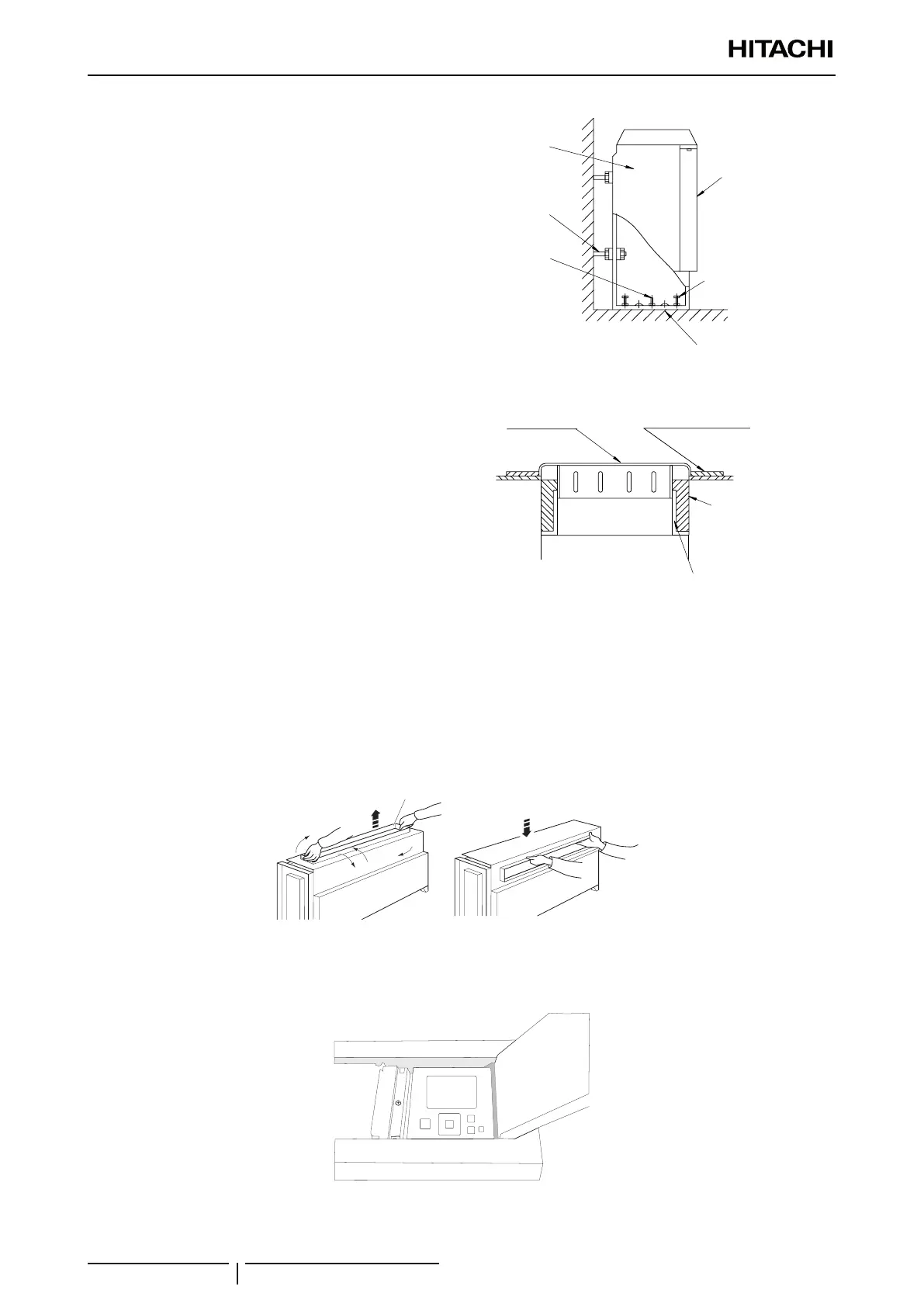
RPF units: carry out the above operation after removing
the front and side covers of the unit.
Side cover
Front cover
Adjustment bolt
for installation
(accessories)
Fixing bolt
Fixing bolt
Fixing screws
RPFI unit: install the optional air outlet grille as indicated
in the gure.
? NOTE
• Condensation may be accumulated if the unit is installed in
a very damp place. Install a porous, water-absorbent plastic
plate to absorb and retain water around the grille.
• The optional air outlet grille of the RPFI unit cannot be used
in very damp places, such as a kitchen or bathroom, as
condensation may settle on its surface.
RPFI units: Install an additional access cover attached
with screws so as not to touch the fan duct directly.
Air outlet ange
Absorbent plate for water
Polyurethane
foam for thermal
insulation
(eld supplied)
Air outlet duct
(eld supplied)
Floor concealed
unit
2.9.3 Change in the air outlet direction (RPFI units)
The air outlet direction of the unit can be modied to adapt it to installation requirements, as shown in the illustration.
1 Lift air outlet -A-.
2 Turn the air outlet on itself until it is opposite its initial position.
3 Tilt the air outlet so that the nozzle is facing forwards.
4 Ret air outlet -A-.
1
2
2
3
4
A
2.9.4 RPF: Optional PC-ARFPE remote control location
It is possible to install the PC-ARFPE remote control below the plastic cover, as shown in the gure.

 Loading...


