6 Optional functions
Indoor units input and output signals
SMGB0099 rev.0 - 12/2016
200
6.1 Indoor units input and output signals
6.1.1 Available ports
The system has eight optional input signals and six output signals. Both types of signal are programmed into the indoor
unit PCB: connector CN3 for input signals and connectors CN7 and CN8 for output signals.
Output connector CN7 has two ports and output connector CN8 has one port, which are used to congure three output
options of the eight available in the system.
? NOTE
The output signal connection is a mere example.
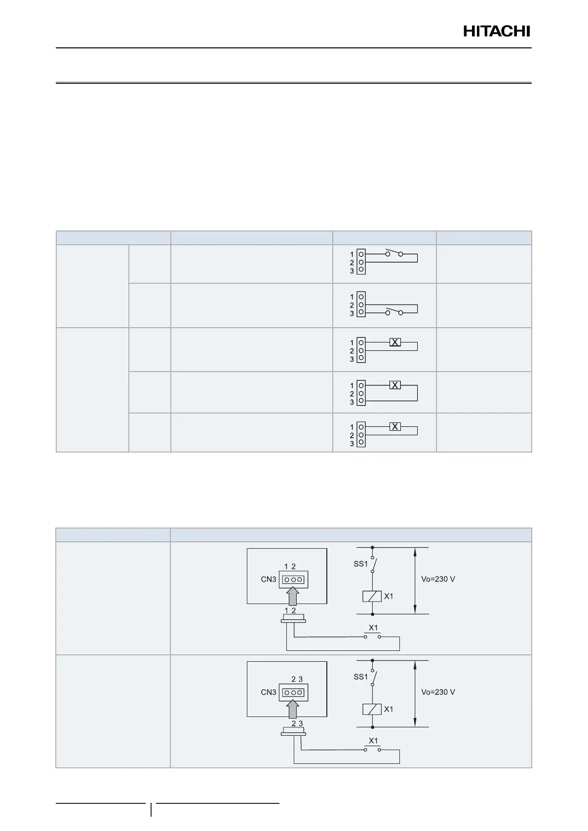
The system has the following input and output ports:
Indication Port setting on the indoor unit PCB Remarks Outlet
Input
i1
CN3 1-2 Contact
i2
CN3 2-3 Contact
Output
o1
CN7 1-2 12 Vdc
o2
CN7 1-3 12 Vdc
o3
CN8 1-2 12 Vdc
? NOTE
o2 Conguration not available for RPI-(16.0/20.0)FSN3PE(-f) units.
The system has the following input connections:
Indication Connections
i1
i2

 Loading...


