6 Optional functions
Indoor units input and output signals
SMGB0099 rev.0 - 12/2016
201
6
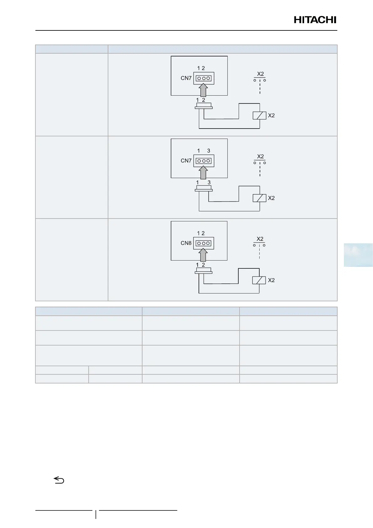
Indication Connections
o1
o2
o3
Component Manufacturer or specications Remarks
Auxiliary relay (X2)
Reduced power relay model
OMRON: MY1F or equivalent
Voltage between the relay
terminals 12 Vdc, 75 mA
Contact (SS1) (x1) (example) Manual type
Voltage between the contactor terminals
230 V, 5 mA
3-pin connector cable
Optional part PCC-1A
(capable of connecting the connector
(JST XHP-3))
Five cables with connectors in one group
Cable (control) Voltage: 12 Vdc 0.5 mm
2
Cable (power) Voltage: 230 V 2.0 mm
2
Recommendations for wiring installation
• Keep the CN3 connector cables as short as possible.
• Try not to pull on the cable along the power line. The cables should be laid separately at a distance of over 30 cm.
Cable crossing is feasible.
• Where the cable along the power line is pulled, insert the cables through a metal pipe, earth one end of the pipe and
install a safety device such as an earth leakage breaker or smoke detector.
• It is recommended to install safety devices such as an electric leakage breaker, etc, (because this is unattended
function).
Returning from optional function setting mode
Press “ ” (return) to return to the normal mode (Operation Mode Indication).

 Loading...


