9 Servicing
RPC-(1.5-6.0)FSN3 - Ceiling type
SMGB0099 rev.0 - 12/2016
289
9
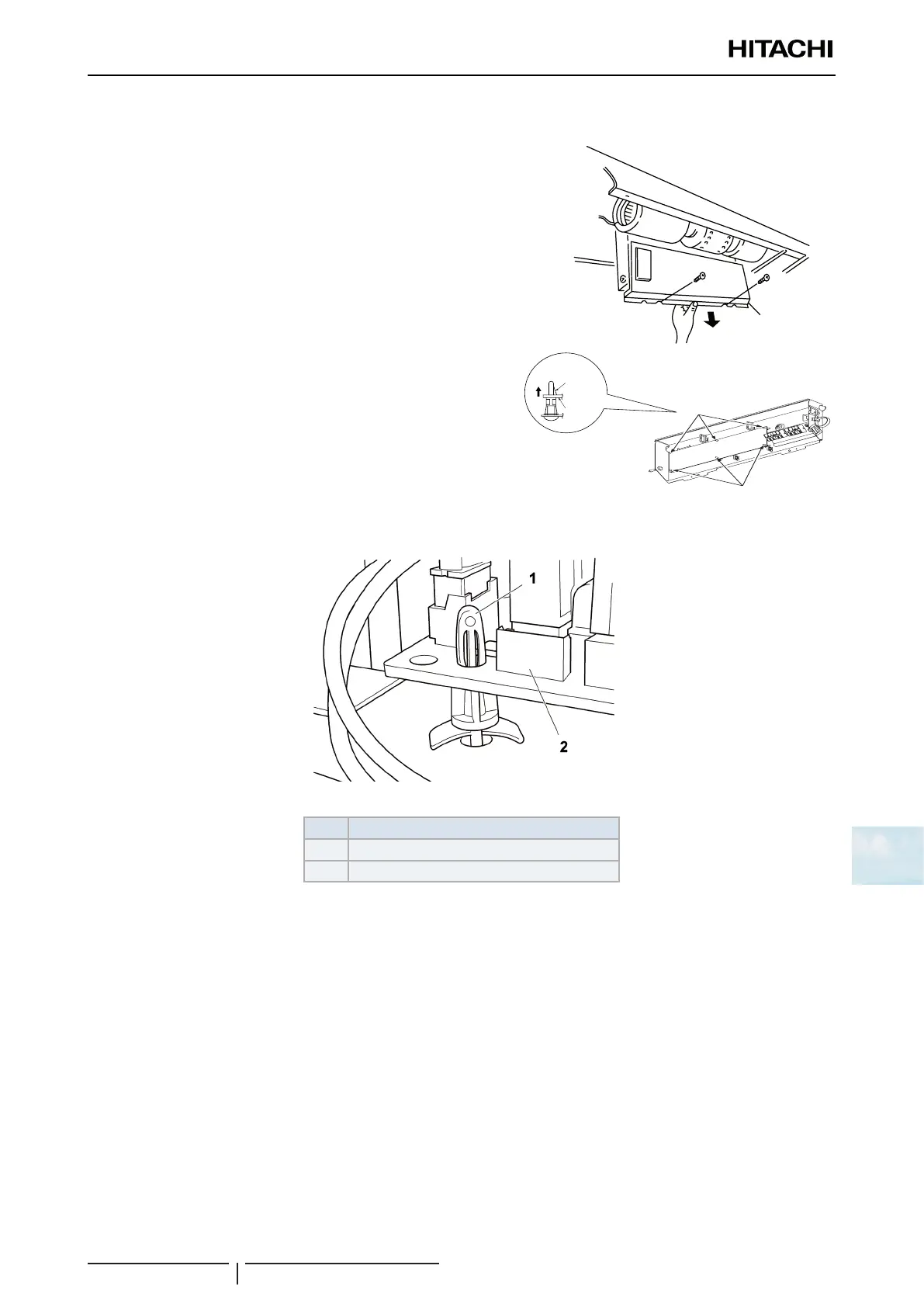
9.5.10 Removal of the printed circuit board (PCB)
1 Open the air inlet grille downward according to “9.5.1 Removing
Air Filter and Air Inlet Grille”.
2 Remove the electrical box and hook it on the ame at the lower
part of the unit according to “9.5.4 Removal of the fan motor”.
3 Remove 2 xing screws for the electrical box cover and remove
it.
4 Remove the 6 holders xing the indoor unit PCB. Pinch the
middle portion with a long-nose pliers and pull them out.
! CAUTION
• Do not touch the electrical components on the PCB.
• Do not apply an excessive force to the PCB nor bend it. Otherwise, it
will lead to a PCB failure
• An incorrect position during installation may damage the PCB.
E-box cover
Holders
Holders
Holder
Middle
portion
Indoor
unit
PCB
Carefully remove the securing supports from the printed control board (PCB) by pressing carefully on the support tabs
with long-tipped pliers.
Nº Part
1 Extended support part
2 PCB
 Loading...


