9 Servicing
RCI-(1.0-6.0)FSN4 - 4-way cassette
SMGB0099 rev.0 - 12/2016
250
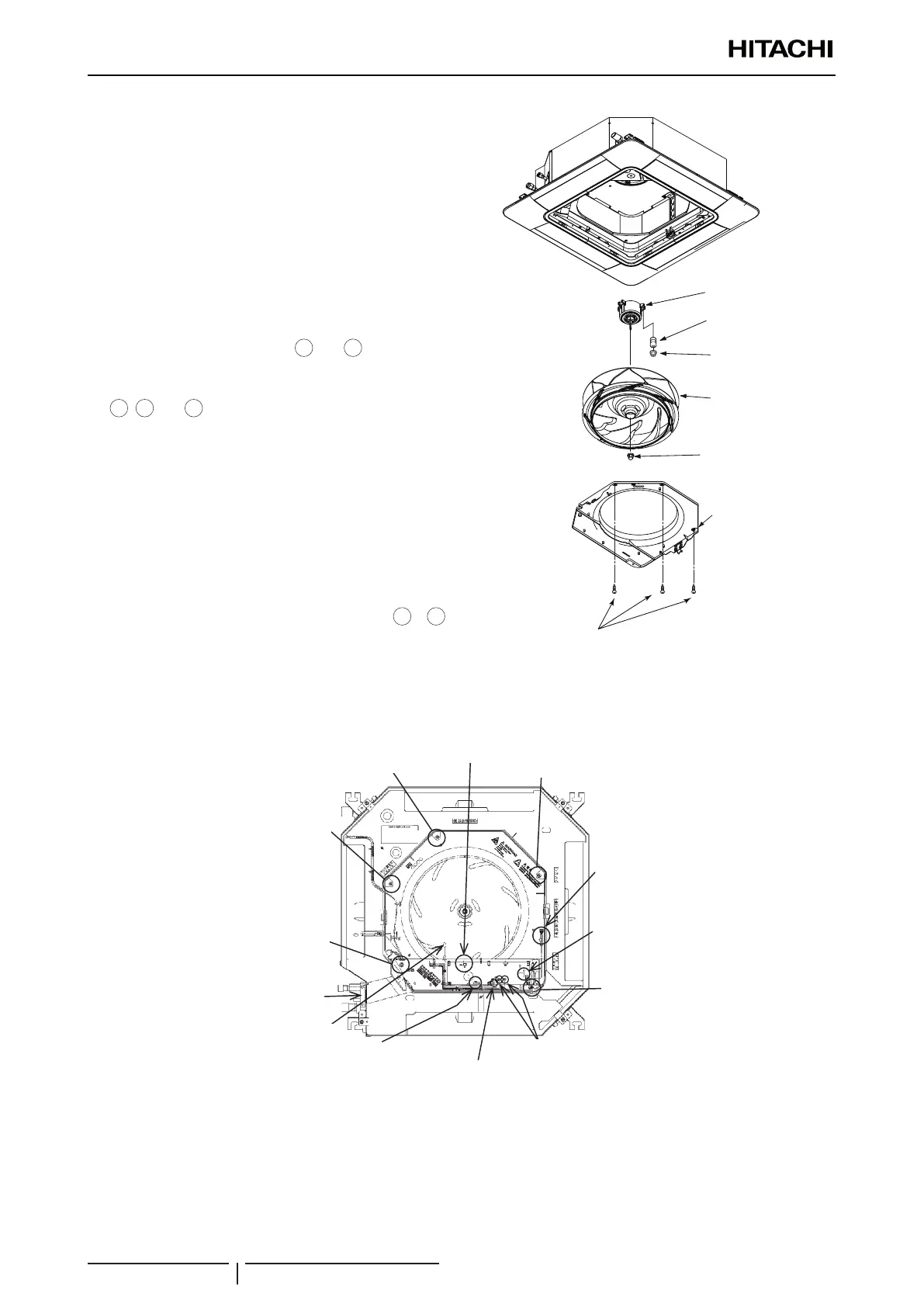
9.1.4 Removing turbo fan and fan motor
1 Remove the air inlet grille and the electrical box cover
according to the item “9.1.1 Removing Air Filter and
Air Inlet Grille” and the item “9.1.2 Removing Electrical
Box Cover”.
2 Moving Electrical Box
a. Remove the outlet air thermistor (THM2), the drain
pump motor connector (PCN6), the oat switch
connector (CN14), the pipe thermistors (THM5 and
THM3), the expansion valve (CN11) and the fan
motor connector (CN1) from indoor unit PCB1.
b. Remove the xing screws
4
and
5
for electrical
box and hang the electrical box from the unit.
3 Removing Bell-Mouth. Remove three (3) xing screws
1
,
2
and
3
for bell-mouth xed to the drain pan,
and remove the bell-mouth.
4 Removing Turbo Fan and Fan Motor
Remove the turbo fan after the xing nut for the turbo
fan is removed. Remove the fan motor after three
(3) xing nuts for the fan motor are removed. (When
reassembling, the tightening torque for nuts shall be
approximately 8N-m.)
? NOTE
When reassembling, temporally x the xing screws (
1
to
5
),
and align the centre of turbo fan and bell-mouth to match.
Tighten securely after keeping the clearance between the turbo
fan and the bell-mouth evenly. In addition, securely x lead wires
for fan motor, 2 pipe thermistors and expansion valve by the cord
clamp attaching at the partition plate.
Fan Motor
Turbo Fan
Fixing Nut
Bell-Mouth
Fixing Screw (3 pcs.)
Fixing Nut (3 pcs.)
Vibration
Fan motor
Vibration absorber
Fixing nut (3 pcs.)
Turbo fan
Fixing nut
Bell-mouth
Fixing screw (3 pcs.)
Fixing screw
Fixing screw
Fixing plate for
electrical wiring
Outlet air
thermistor (THM2)
Fan motor
connector (CN1)
Float switch
connector (CN14)
Pipe thermistor (THM5, THM3)
Fixing screw
Fixing screw
Fixing screw
Expansion valve
(CN11)
Drain pump motor
connector (PCN6)
CN36

 Loading...


