9 Servicing
RPC-(3.0-6.0)FSN3E - Ceiling type
SMGB0099 rev.0 - 12/2016
280
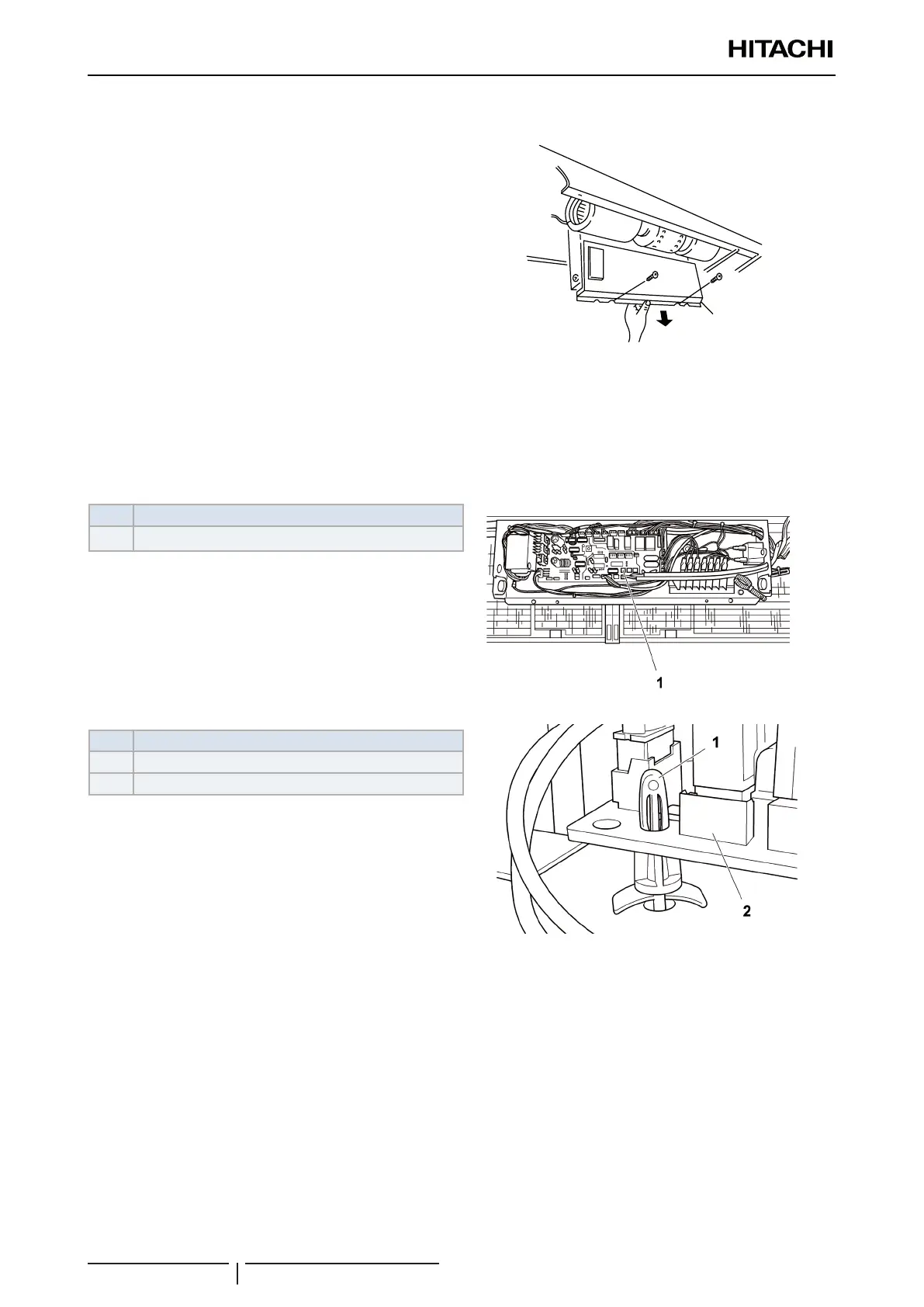
9.4.9 Removal of the printed circuit board (PCB)
1 Open the air inlet panel as indicated in chapter “9.4.1
Removal of the air lter”.
2 Separate the connector from the fan motor wiring.
3 Remove the screws securing the box and attach to the
lower frame.
! CAUTION
Hold onto the electrical box to prevent it from falling.
4 Remove the panel.
E-box cover
5 Carefully remove the securing supports from the printed control board (PCB) (four) by pressing carefully on the
support tabs with long-tipped pliers.
! CAUTION
• Do not touch the electrical components of the PCB.
• Do not apply force to the PCB, as this could damage it.
• Pay special attention to the position of the connectors on the PCB. An incorrect position during installation may damage the PCB.
Nº Part
1 PCB
Nº Part
1 Extended support part
2 PCB

 Loading...


