4 Electrical and control settings
Unit electrical wiring and connection
SMGB0099 rev.0 - 12/2016
137
4
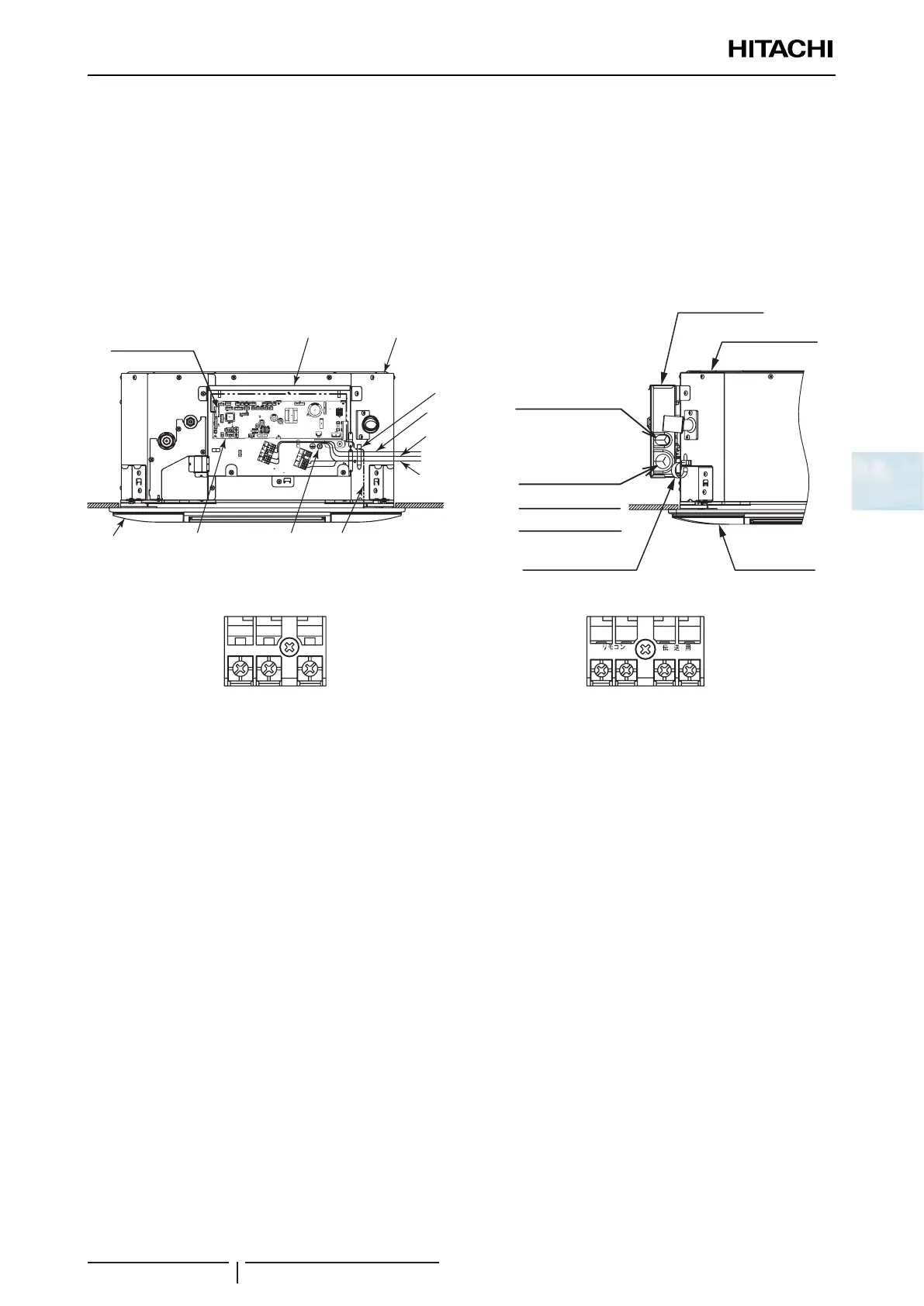
Electrical connection
Make the connection between the indoor unit and the air panel.
? NOTE
• To prevent the screws from falling from the terminal box, do not remove them completely, hold onto the terminal and check that the
screw is secure through the hole in the terminal.
• Use the following screws for the terminal box:
- M4 screw for the power supply.
- M3.5 screw for the operating line.
Electrical box
Remote control switch cable
Control cable
Power source cable
Indoor unit
Air panel
Cable for auto swing motor
Wire clamp
ON
12
Electrical box
Wire clamp
Air panel
Indoor unit
Connector (CN17)
Earth
screw
Control cable
Remote control
switch cable
Power
source cable
PCB
Cable for auto
swing motor
Terminal Board 1 Terminal Board 2
-
S/NR/L1
Terminal board for Power
source cable
AB
Terminal board for Control
source cable
Follow the steps below to connect the remote control cable or the optional extension wire:
1 Pass the cable through the knock-out hole in the cabinet.
2 Connect the cable to terminals A and B of the terminal strip (TB2).
3 Tighten the screw on terminals A and B.
4 Check that the cables are correctly secured.
Follow the steps below to connect the power cables to the terminal strip (TB1):
! CAUTION
• To connect a power supply with neutral, connect the cables to terminals L1 and N on the terminal strip (TB1).
• To connect a power supply without neutral: make the connection to terminals L1 and L2 on the terminal strip (TB1).
1 Where necessary, loosen the screws on terminals L1 and N or L1 and L2, as applicable, on the terminal strip (TB1).
2 Connect the power cables to terminals L1 and N or L1 and L2, as applicable.
3 Tighten the screws on terminals L1 and N or L1 and L2, as applicable.
4 Check that the cables are correctly secured.
Follow the steps below to connect the communication cables between the outdoor and indoor unit to the terminal strip
(TB2):
1 Where necessary, loosen the screws on terminals 1 and 2 on the terminal strip (TB2).
2 Connect the communication cables to terminals 1 and 2.
3 Tighten the screw on terminals 1 and 2.
4 Check that the cables are correctly secured.
 Loading...


