4 Electrical and control settings
Unit electrical wiring and connection
SMGB0099 rev.0 - 12/2016
139
4
Follow the steps below to connect the communication cables between the outdoor and indoor unit to the terminal strip
(TB2):
1 Where necessary, loosen the screws on terminals 1 and 2 on the terminal strip (TB2).
2 Connect the communication cables to terminals 1 and 2.
3 Tighten the screw on terminals 1 and 2.
4 Check that the cables are correctly secured.
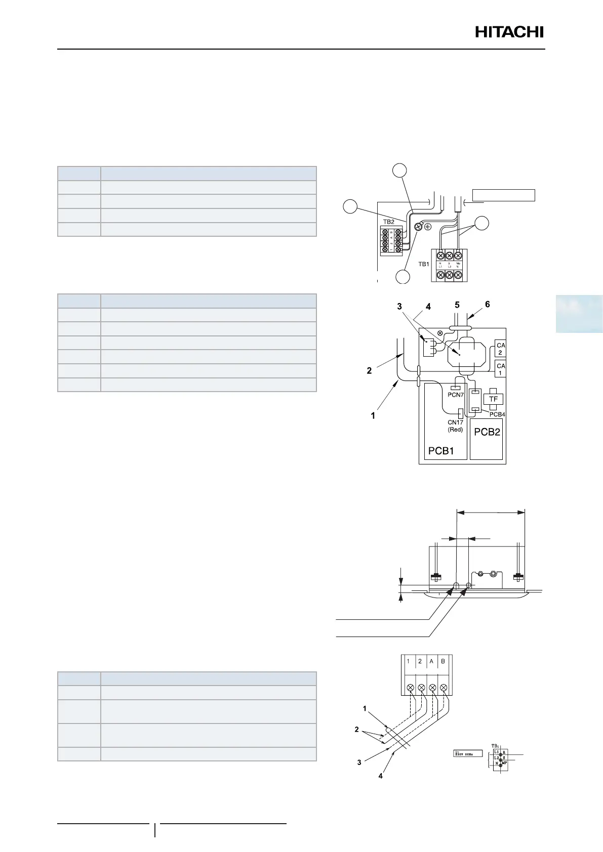
Nº Part
1 Control Cable
2 Remote Control Cable
3 Power Source Cable
4 Earth Screw
1
2
3
4
1N 220-240V/50Hz
Nº Part
1 Connector for the swing louver motor
2 Fan motor connector
3 Terminal strip (TB2)
4 Terminal strip (TB1)
5 Wiring
6 Power wiring
Follow the steps below to connect the earth wire to the earth connection in the electrical box:
1 Where necessary, loosen the screw on the earthing connection
in the electrical box.
2 Connect the shielded part of the power supply earth wire and
the signal wiring earth wire to the earth connection.
3 Tighten the screw on the earthing connection in the electrical
box.
4 Check that the shielded part of the earthing cables are
correctly secured.
90
50
Wiring hole (30-39)
Wiring hole
(Ø32.5 knock-out hole)
Nº Part
1 Tie
2
Communication wiring between the indoor and outdoor
units and between indoor units
3
Operating control wiring. In the case of group operations
using a remote control
4 Remote control wiring
Power source

 Loading...


