4 Electrical and control settings
Wiring diagrams for indoor units and complementary systems
SMGB0099 rev.0 - 12/2016
171
4
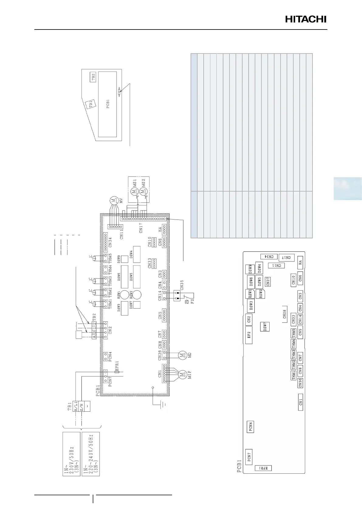
Wiring diagrams for the RCD-(0.8-3.0)FSN3 indoor units(with air panel P-AP90DNA)
Mark Name
CN3 Optional connector (for signal input)
CN7, 8 Optional connector (for signal output)
CN10 Optional connector (for motion sensor)
DSW3, 4, 7, 9 Dip Switch for setting
EFR1 Fuse
MIF Motor for indoor fan
MS Motor for automatic swing louver
MV Micro computer control expansion valve
MD Motor for Drain discharge mechanism
PCB1 Printed circuit board
RSW1 Rotary switch for unit Nº setting (Units digit)
DSW6 Dip switch for unit Nº setting (Tens digit)
RSW2 Rotary switch for refrigerant cycle Nº setting (Units digit)
DSW5 Dip switch for refrigerant cycle Nº setting (tens digit)
TB1,2 Terminal block
THM1~3, 5 Thermistor
THM4 Optional connector (for remote temperature sensor)
CN4~6, HA, PCN4 Reserved connector on PCB
Factory wiring
Earth wiring
Field wiring
Optional parts
Field connection
◆
Field connection
◆
►
Remote
control
switch
Operating
line DC5V
Field connection
◆
►
► Air panel
Electrical control
box of Indoor unit
Optional Service connectos for
Drain discharge mechanism
Printed circuit board
(Air
inlet)
(Air
outlet)
(Freeze
protection)
(Gas
piping)
(Remote)

 Loading...


