4 Electrical and control settings
Wiring diagrams for indoor units and complementary systems
SMGB0099 rev.0 - 12/2016
178
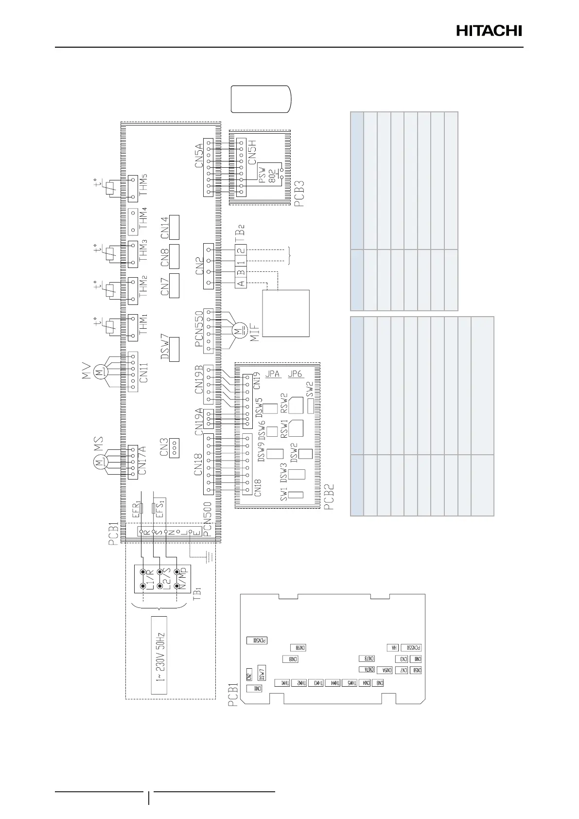
Wiring diagrams for the RPK-(0.6-1.5)FSN3M indoor units
Mark Name
CA Capacitor
TB1, 2 Terminal board
PCB1~4 Printed circuit board
PCN4,7 Connector on PCB
CN3~19 Connector on PCB
PCN500,550 Connector on PCB
RSW1, 2 Rotary switch
DSW2~9, SW1 Dip switch for settings
MV
Micro-computer control expansion
valve
Mark Name
MIF Motor for Indoor fan
MS Motor for automatic swing louver
THM1~5 Thermistors
EF,R1,S1 Fuse
PSW802 Emergency operation switch
SW1,2 Wired RCS/Wireless RCS
RSW1,2 Rotary switch
Air inlet
Air outlet
Freeze
protection
Gas
piping
Wired
remote
control
switch
Wireless
remote
control
switch
Operation line
DC 5V
Wireless receiver
& indication part

 Loading...


