6 Optional functions
Complementary systems
SMGB0099 rev.0 - 12/2016
229
6
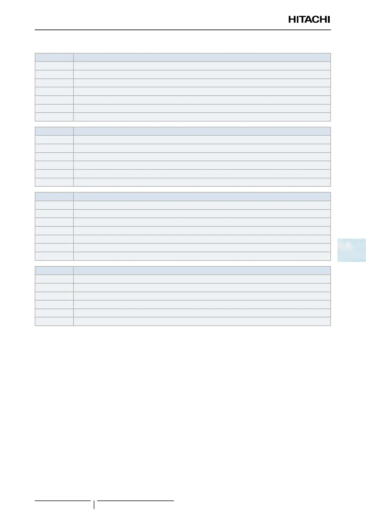
DX-Interface series 2 - Input / Output signals
Input signal Available from DX-Interface series 2
1 Control using the eld-supplied room thermostat (cooling).
2 Control using the eld-supplied room thermostat (heating).
3 Function 1 - remote ON/OFF of the unit (by contact).
4 Function 2 - turns unit ON.(by pulse).
5 Function 2 - turns unit OFF.(by pulse).
6 Cancellation of commands from remote control switch after forced stoppage.
7 Setting of the cooling mode or the heating mode.
Output signal Available from DX-Interface series 2
1 Operation signal.
2 Alarm signal.
3 Cooling signal.
4 Thermo-ON signal.
5 Heating signal.
6 Defrost signal.
Input signal Available from Outdoor unit
1 Control using the eld-supplied room thermostat (cooling).
2 Control using the eld-supplied room thermostat (heating).
3 Function 1 – remote ON/OFF of the unit (by contact).
4 Function2 - turns unit ON (by pulse).
5 Function2 - turns unit OFF (by pulse).
6 Cancellation of commands from remote control switch after forced stoppage.
7 Setting of the cooling mode or the heating mode.
Output signal Available from Outdoor unit
1 Operation signal.
2 Alarm signal.
3 Cooling signal.
4 Thermo-ON signal.
5 Heating signal.
6 Defrost signal.
Thermo - On / Off control option
With DX-Interface series 2 it is possible to perform the thermo-On/thermo-Off control by three different ways.
• Standard thermo-On / thermo-Off control (Default setting).
Suitable for installations controlled by suction or discharge temperature.
The thermo-On / thermo-Off logic is decided based on the difference between the inlet temperature to the coil and the
set temperature on the remote controller or central controller.
• By an external input.
The thermo-On / thermo-Off control can be driven externally by an input signal connected to the CN3 socket of the
PCB1 of the DX-Kit.
Setting NOTE: DIP Switch 1 – Pin 6 of DX-Kit PCB2 (small PCB) must be switched on (PCB2-DSW1#6 switched
ON).
Once the PCB DSW has been set, the input “i1” of CN3 is automatically set for thermo-On / thermo-Off control. The
setting of input “i2” is kept as set on the remote controller.
Please refer to HITACHI Indoor Units Service Manual for further information about the setting and connection of the
auxiliary inputs to CN3 socket.
 Loading...


