9 Servicing
RPK-FSN(H)3M - Wall mounted
SMGB0099 rev.0 - 12/2016
316
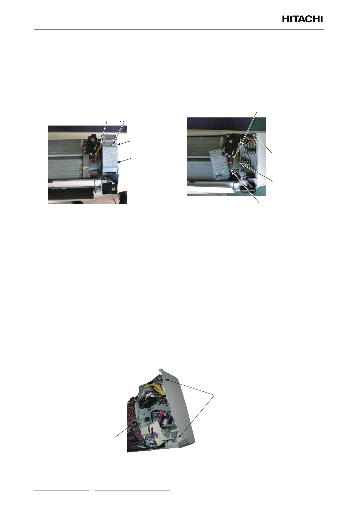
5 Remove the wirings for the freeze protection thermistor, gas pipe thermistor, inlet air thermistor and the expansion
valve coil from the wiring outlet at the upper part. Also remove the wirings for the outlet air thermistor, auto-louver and
fan motor from the wiring outlet at the lower part.
6 Remove 2 screws xing the electrical box to dismount it from the indoor unit body.
? NOTE
If the unit with the expansion valve kit is used, regard “expansion valve coil” as “expansion valve relay cord.”
Screw for
Electrical Box Cover
Screw for
Terminal Board Cover
Electrical Box
Cover
Terminal Board Cover
and Switch Cover
Screw for electrical
box cover
Screw for terminal
board cover
Electrical box
cover
Terminal board
cover and
switch cover
Screw for
Electrical Box
Screw for
Electrical Box Cover
Earth Wiring
Screw for Earth Wiring
Screw for earth wiring
Screw for electrical
box
Screw for electrical
box cover
Earth wiring
For RPK-(2.0-4.0)FSN(H)3M
1 Remove the front panel according to the “9.9.2 Removal of the front panel” chapter
2 Remove the terminal board cover and the electrical box cover according to “9.1.5 Removing Printed Circuit Board
(PCB1)” chapter
3 Then, remove the power source wiring, the transmission wiring and the wiring for the remote control switch from the
terminal board.
4 Remove the connectors (on the PCB1) for the freeze protection thermistor, gas pipe thermistor, inlet air thermistor,
outlet air thermistor, auto-louver, PCB for indication, PCB for receiver, fan motor and expansion valve coil.
5 Remove the wirings for the freeze protection thermistor, gas pipe thermistor, inlet air thermistor, fan motor and
expansion valve coil from the wiring outlet at the upper part. Also remove the wirings for the outlet air thermistor, auto-
louver, PCB for indication and PCB for receiver from the wiring outlet at the lower part.
6 Remove 2 screws xing the electrical box to dismount it from the indoor unit body.
7 Remove the earth screw to disconnect earth wire between the heat exchanger and the electrical box.
8 Before remounting the electrical box, make sure to connect the connectors mentioned above. Then mount the
electrical box in the reverse procedure.
? NOTE
If the unit with the expansion valve kit is used, regard “expansion valve coil” as “expansion valve relay cord.”
Screws for
Electrical Box
Earth Screw
Screw for electrical box
Earth screw

 Loading...


