77 Using four 6-by-2 test connectors, four BNC Couplers, and four SMA (m) - BNC (f)
Adapters, connect the logic analyzer to the pulse generator channel outputs. To
make the test connectors, see chapter 3, "Testing Performance."
aa Connect the even-numbered channels of the lower byte of the pod under test to the
pulse generator channel 1 Output and J-clock.
bb Connect the odd-numbered channels of the lower byte of the pod under test to the
pulse generator channel 1
Output.
cc Connect the even-numbered channels of the upper byte of the pod under test and the
clock channel to the pulse generator channel 2 Output.
dd Connect the odd-numbered channels of the upper byte of the pod under test to the
pulse generator channel 2
Output.
88
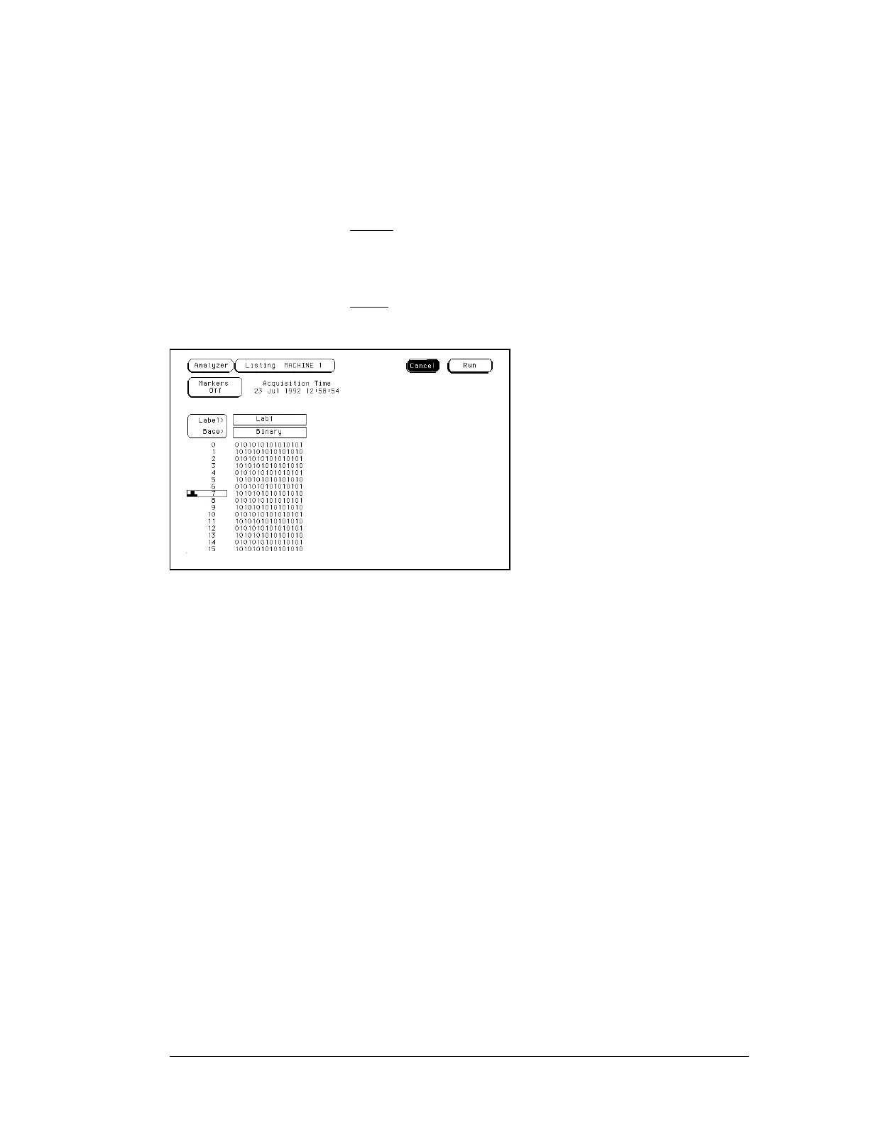
On the logic analyzer, press Run. The display should look similar to the figure below.
99 If the display looks like the figure, then the cable passed the test.
If the display does not look similar to the figure, then there is a possible problem
with the cable or probe tip assembly. Causes for cable test failures include the
following:
•
open channel.
•
channel shorted to a neighboring channel.
•
channel shorted to either ground or a supply voltage.
Return to the troubleshooting flowchart.
Troubleshooting
To test the logic analyzer probe cables
5–32

 Loading...


