Marker FunctionsMarker Functions
Time IntervalT i me I nt er val The X and O markers measur e t he t ime int erval bet ween a point on a
timing waveform and the t rigger, t wo points on the same t iming waveform, t wo points on
different waveforms, or two states (time tagging on).
Delta States Delt a St at es ( stat e analyzer only)( st at e analyzer only) The X and O markers measure the number of
tagged states between one state and trigger or between two states.
Pat t ernsPat t erns The X and O markers can be used to locate the nth occurrence of a specified
pattern from trigger, or from t he beginning of data. The O marker can also find the n th
occurrence of a pattern from the X marker.
St at i st icsSt at i st i cs X and O mar ker st at ist ics are calculat ed for repet it ive acquisit ions. Pat t erns
must be specified for both markers, and statistics are kept only when both patterns can
be found in an acquisition. Statistics are minimum X to O time, maximum X to O time,
average X to O time, and ratio of valid runs to total runs.
Auxiliary PowerAuxiliary Power
Power Through Cables 1/3 amp at 5 V maximum per cable
Operating EnvironmentOperating Environment
Temperature Instrument, 0 °C to 55 °C ( +32 °F to 131 °F) .
Probe lead sets and cables,
0 °C to 65 °C ( +32 °F to 149 °F).
Humidity Instrument, probe lead sets, and cables, up to
95% relative humidity at +40 °C (+ 122 °F).
Altitude To 4600 m ( 15,000 ft) .
Vibration Operating: Random vibration 5 to 500 Hz,
10 minutes per axis, ≈ 0.3 g ( rms) .
Non-operating: Random vibration 5 to 500 Hz,
10 minutes per axis, ≈ 2.41 g ( rms) ;
and swept sine resonant search, 5 to 500 Hz,
0.75 g (0-peak) , 5 minute resonant dwell
at 4 resonances per axis.
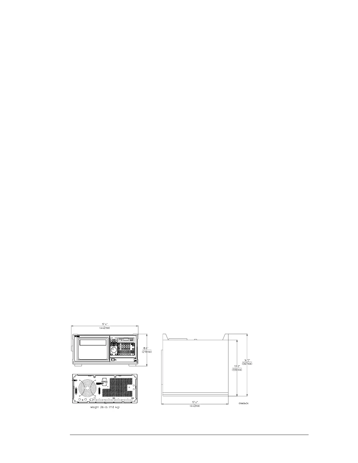
DimensionsDimensions
General Information
Supplemental Characteristics (logic analyzer)
1–8

 Loading...


