HT2800T_en_c.doc Page 57 of 275
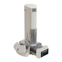
1 Needle Guide regulator (right block)
2 Safety lock (left block)
3 Vial locator
In order to set the regulating lock, please proceed as follows:
1. Open the syringe location by pushing up the sliding lid (see Figure 10).
2. Lower the sledge manually to have free access to the left block (safety lock) as shown in
Figure 61 (from a to c).
3. Loosen the left block (safety lock) using the supplied syringe pointer (see Figure 31) as
shown in Figure 60.
4. Let the right block move down until it rests on the sledge.
5. Lift the left block about 2-3mm above the right block level and lock it.
6. Verify that the vial locator can be lifted freely by hand. If not, verify that the right and left
block are locked parallel.
6. Close the sliding lid.
3.3.3 Electrical connections
Warning
Check that the autosampler is switched OFF. Do not use a power supply system different from the
one supplied with this unit. This could cause damage to the autosampler or to the person using it.
Warning
If you don’t adjust the safety lock, after start up the autosampler will display an error
message (see paragraph 8 Troubleshooting8 “Troubleshooting“). For an accurate first
installation, do not release the needle guide regulator – right block (see paragraph
4.2.2 “Setup: Syringe warmer assembly installation/ replacement (Headspace mode)”.