D.6 Part. N. 8000 H1344 (10-2009)
SETTINGS AND ADJUSTMENTS
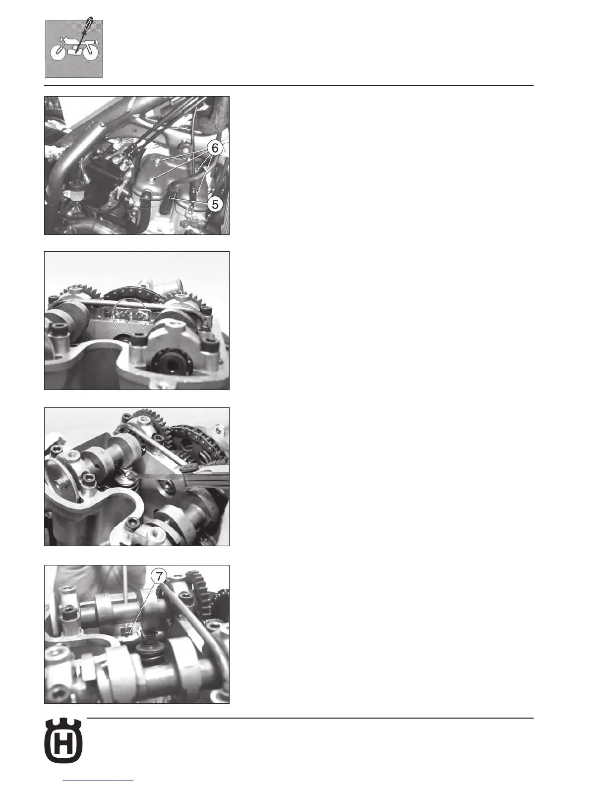
PROCEDURE APPLYING TO ALL THE MODELS
Remove the spark plug (5), the four cylinder head cover fastening screws (6)
and the cylinder head cover.
Engage second gear and, moving the vehicle forwards and backwards, bring
the piston to Top Dead Center (in this condition , the mark on the cylinder head
is aligned with the two marks on the idle gear of the camshafts, as illustrated
in the gure).
Check, by means of a feeler gauge, that the valve clearance is 0,10÷0,15 mm
for INTAKE and 0,15÷0,20 mm for EXHAUST;
Otherwise, lift the retaining clip (7) using a hook, let the rocker arm slide to one
side, extract the pad with a pair of pliers and check the thickness;
Depending on the result, t a new pad (as spare parts, pads are supplied ranging
from 1.60 mm to 2.60 mm in steps of 0.05 mm) and return the clip and rocker arm;
Check the valve clearance again and, if it’s correct, reassembly the removed
parts using the reverse procedure.