Y.9Part. N. 8000 H1344 (10-2009)
FRAME AND WHEELS
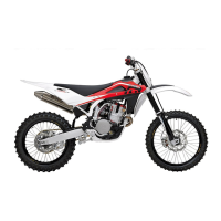
Tighten the screw (3) on the fork L.H. side but DO NOT lock it. Now, pump for a
while, pushing the handlebar downwards until you are sure that the fork legs are
perfectly aligned. Lock: the screws (1) on the R.H. leg (10,4 Nm/ 1,05 Kgm/ 7.7
ft-lb), the screw (3) on the L.H. side (51,45 Nm/ 5,25 Kgm/ 38 ft-lb), the screws
(1) on the L.H. leg (10,4 Nm/ 1,05 Kgm/ 7.7 ft-lb).
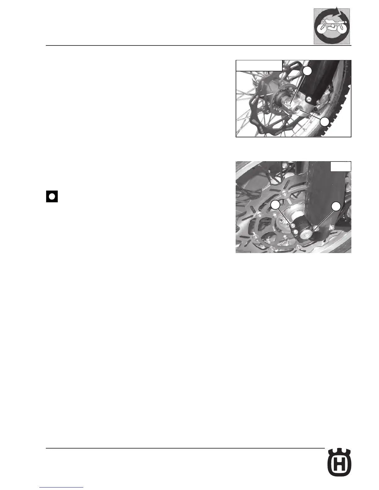
SMR: t the brake caliper on the disc; assemble the caliper on its holding plate
and tighten the screws (A) at 25,5 Nm/ 2,6 Kgm/ 18.8 ft-lb.
Check that the brake disc slides between the caliper pads without any friction.
Check the distance between magnet on the brake disc and sensor on the brake
caliper (page I. 61).
After reassembly, pump the brake control lever until the pads are against
the brake disc.
TE-TC-TXC
1
3
2
1
SMR