4. Operation
4.2 Operation in Positioner Mode
4-16
ME0342-4B
(7) Threshold [%] :
Set the threshold value of the pressing torque in percent [%].
If the torque (load current) becomes larger than this setting value during pressing, the
detection signal is output. This feature is used to monitor the load current and judge
whether the operation is good or not in such an operation as press fitting in pressing.
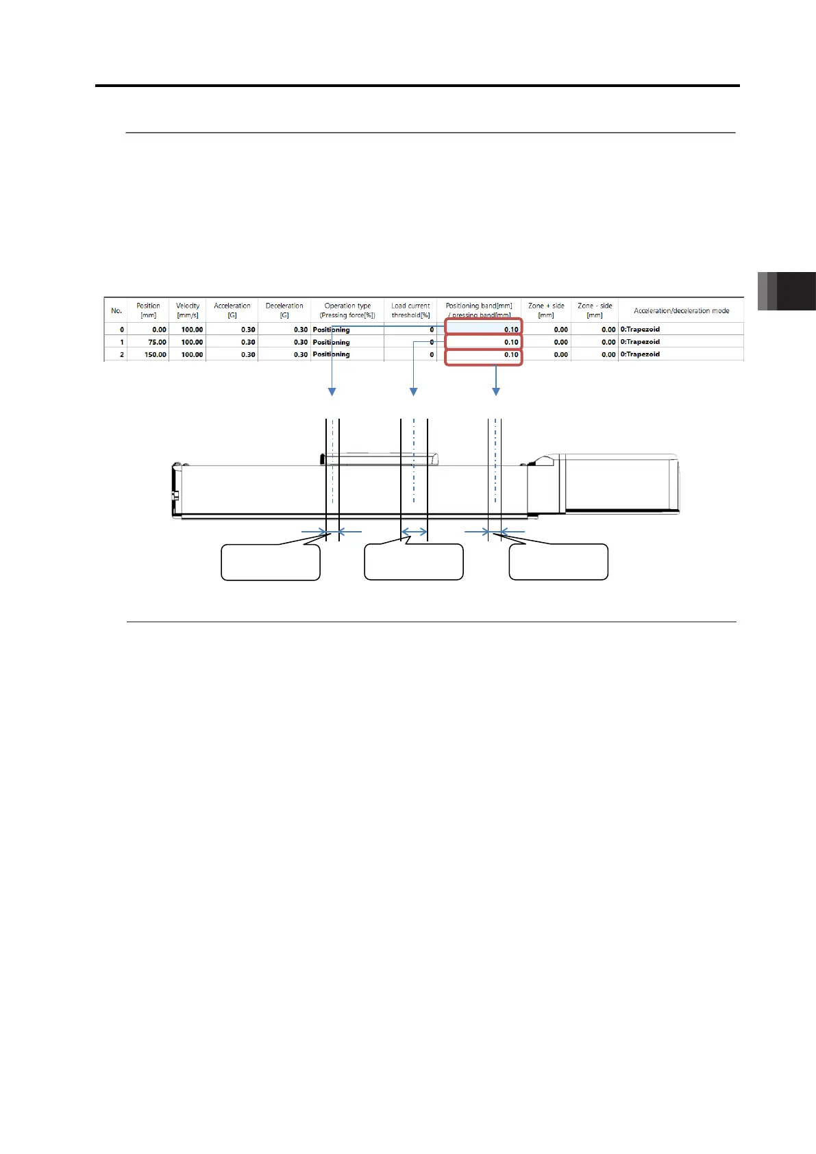
(8) Positioning width [mm] :
For positioning in PIO patterns
(Note 1)
0 to 4, the positioning complete signal is output if the
remaining moving distance is entered within the zone set here.
For the pressing operation, the actuator should move in the same velocity and
acceleration/deceleration as those set for the normal positioning till it reaches the point set
in (2), and then starts pressing drive for the amount of data set in this section.
For PIO pattern 5, this item is not the complete signal output range against positioning
command. Just as it does in detection with a sensor, the applicable output signal (LS*)
should turn ON once the actuator gets in the range of the setting values regardless of the
indicated position number. PIO pattern 5 does not correspond to the pressing operation.
Make sure to set a value of the minimum positioning width or higher for the positioning
width.
(For 800 pulse encoder)
Min. Positioning Width = Lead Length / 800 (Number of Encoder Pulse) × 3
(For 8192 pulse encoder)
Min. Positioning Width = Lead Length / 8192 (Number of Encoder Pulse)
Note 1 PIO pattern: This is the operation pattern of Positioner mode.
Refer to [2.2.2 [1] PIO Patterns in Positioner Mode]
signals is turned ON. If the actuator passes any of the positioning bands in the
turned ON. PZONE is set to ON in the zone between this value and the coordinate value on
is turned ON.

 Loading...


