4. Operation
4.2 Operation in Positioner Mode
4-36
ME0342-4B
4.2.5 Operation with the Position No. Input (PIO Patterns 0 to 3 and 6)
This section describes the methods of operations of PIO patterns 0 to 3 and PIO pattern 6.
These patterns provide normal controller operation methods in which the controller is operated
by turning the start signal ON after a position No. is entered.
PIO Pattern 6 is dedicated for the force sensor used pressing. It is for operation of an actuator
equipped with a loadcell and is capable of pressing control with high precision. It is necessary to
have the initial setting established for calibration and parameters before operation.
Refer to [4.2.8 Preparation for Operation in Force Sensor Pressing (Loadcell Calibration)]
The control methods of positioning, pitch feed, and pressing are the same as those described
before.
Note PIO Pattern 6 is applicable only for PCON-CBP/CGBP.
[1] Positioning [Basic]
(PC1 to PC**, CSTR, PM1 to PM**, PEND, MOVE, LOAD, TRQS)
PIO signal
PIO pattern 2 PC1 to 128
PM1 to 128
× × ×
: Available, ×: Unavailable
Note For incremental type, operation without home return leads the operation based on the
data of the specified position No. after automatic home return. If one or more problems
are found, interlock by home return complete signal HEND is required.
In the battery-less absolute or simple absolute type, if it gets into a condition that the
home-return operation is incomplete due to such a reason as a parameter change,
operation to the indicated position number would not be performed, but only the home-
return operation should be performed.
■ Sample use
4.2 Operation in Positioner Mode
ME0342-4B 4-37
■ Control method
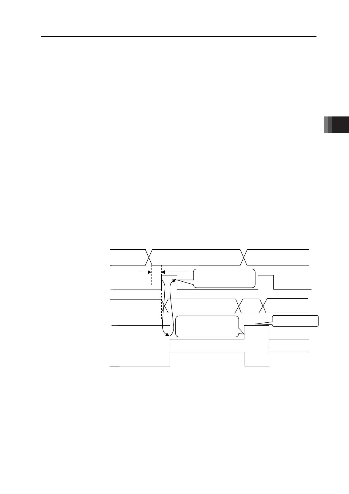
1) First enter command position No. PC1 to PC** with binary data. Next turn start signal CSTR
ON. Then the actuator starts acceleration depending on the data in the specified position
table for positioning to the target position.
2) At operation start, positioning complete signal PEND is turned OFF. Always turn the CSTR
signal OFF. Without it, the completed position number is not output and the positioning
complete signal is not turned ON at the completion of positioning.
3) When the positioning is completed, the positioning complete position numbers are output
from complete position No.PM1 to PM** with binary data and also positioning complete
signal PEND is turned ON.
4) Moving signal MOVE is turned ON as soon as the operation is started and turned OFF at the
completion of positioning.
5) Positioning complete signal PEND is turned ON if the remaining moving distance enters into
the positioning width. PEND Signal will be kept ON once it is turned ON unless the start
signal CSTR is turned back ON, servo is turned OFF
(Note 1)
or the actuator is out of the
positioning band width range
(Note1)
.
Note 1 It can be switched over with Parameter No.39.
Note 1 The completion position No. output is set to 0 during movement of the actuator.
PC1 to PC**
(PLC→Controller)
PM1 to PM**
(Controller→PLC)
(PLC→Controller)
Positioning Completion Signal
PEND
(Controller→PLC)
Moving Signal MOVE
(Controller→PLC)
(Note 1)
(Note 1)
turning PEND OFF
entering into

 Loading...


