4. Operation
4.2 Operation in Positioner Mode
4-92
ME0342-4B
(Example) Repetition of ST1 → ST2 → ST1 →• • •
Insert timer Δt if necessary.
Δt : Time required to certainly reach the target position after the position sensing output LS1 or 2 is turned on.
[Example of stop position when the ST* signal is turned OFF by the LS* signal]
If the positioning width is set at a position before the original deceleration start position,
the actuator cannot reach the target position.
entering into
positioning width zone
Stop before target position
Orignal deceleration
start position
4.2 Operation in Positioner Mode
ME0342-4B 4-93
Caution
● If the ST* signal for the position is turned ON after the completion of positioning, the LS*
signal remains ON.
● Both the LS* and PEND signals are set to ON in the positioning width zone. Accordingly,
they may be turned ON under operation of the actuator if a large positioning width is set.
● Interlock should be taken so that two or more ST* signals are set to ON simultaneously.
If two or more ST* signals are input simultaneously, they will be executed according to
the following priorities: ST0 → ST1 → ST2.
● LS* signal would not be output if the positioning width is set less than the minimum
resolution.
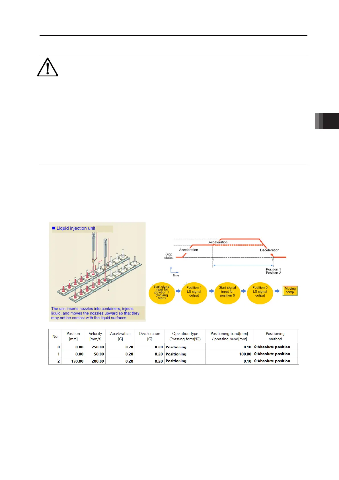
[4] Speed Change During the Movement
■ Sample use
■ Control method
The speed of the actuator can be changed while it moves. The operation control method is the
same as that in [3] Positioning. This pattern prioritizes the startup signal commanded first.
Therefore, when another position number is started during an operation and the first startup
signal is turned OFF, and then the new position number condition starts to operation at this
moment (velocity change).
Positioning complete width at position 1

 Loading...


